1. Introduction
This manual provides detailed instructions for the safe and efficient operation, installation, and maintenance of your Briidea BR-159 Salt Chlorine Generator. This device is designed to provide a chemical-free sanitization solution for hot tubs and swim spas up to 2000 gallons, utilizing a USA-made titanium salt cell to produce chlorine from salt.
Please read this manual thoroughly before installation and use to ensure optimal performance and longevity of your unit.
2. Safety Information
Always follow basic safety precautions to reduce the risk of fire, electric shock, and injury to persons, including the following:
- Read all instructions before using this product.
- Do not operate the unit if the power cord or chlorinator cell is damaged.
- Ensure the power outlet is protected by a Ground Fault Circuit Interrupter (GFCI).
- Keep the controller above ground and away from water splashes.
- Always disconnect power before performing any maintenance or cleaning.
- This device is intended for hot tubs and swim spas up to 2000 gallons. Do not use for larger volumes.
3. Package Contents
Verify that all components are present:
- Briidea BR-159 Salt Chlorine Generator Controller
- Chlorinator Cell with Cable
- Power Adapter
- Instruction Manual (this document)
4. Specifications
| Model Number | BR-159 |
| Product Dimensions (Controller) | Approximately 3.9 x 5.6 inches (width x height) |
| Product Dimensions (Cell) | Approximately 2.3 x 5.6 inches (diameter x height) |
| Item Weight | 2.33 pounds (1.06 Kilograms) |
| Manufacturer | briidea |
| Recommended Spa Volume | Up to 2000 Gallons |
| Electrode Lifespan | Up to 3,000 hours (USA Titanium) |
| Key Features | LED Indicator, Built-in Timer/Controller, Salt Concentration Detection |
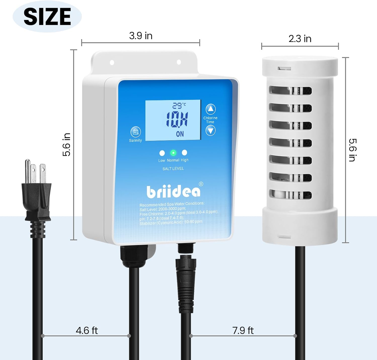
Figure 1: Dimensions of the Briidea BR-159 Salt Chlorine Generator controller and cell.
5. Setup and Installation
The Briidea BR-159 Salt Chlorine Generator is designed for easy installation without the need for complex plumbing. Follow these steps:
- Prepare Your Spa/Hot Tub: Ensure your hot tub or swim spa is clean and filled with water.
- Add Salt: Add appropriate pool/spa salt (sodium chloride) to your water. The recommended salt level for optimal operation is typically between 2000-3000 ppm (parts per million). Refer to your spa's volume to calculate the required amount of salt. Dissolve the salt completely before proceeding.
- Position the Controller: Mount the controller unit above ground in a dry, protected area, away from direct water exposure. Ensure it is within reach of a GFCI-protected power outlet.
- Submerge the Chlorinator Cell: Place the chlorinator cell directly into the hot tub or swim spa water. Ensure it is fully submerged and positioned where water can circulate freely around it.
- Connect Power: Plug the chlorinator cell's cable into the controller, then plug the controller's power adapter into the GFCI-protected electrical outlet.
- Initial Check: The LED indicators on the controller will display the current salt level (Low, Normal, High) and water temperature.
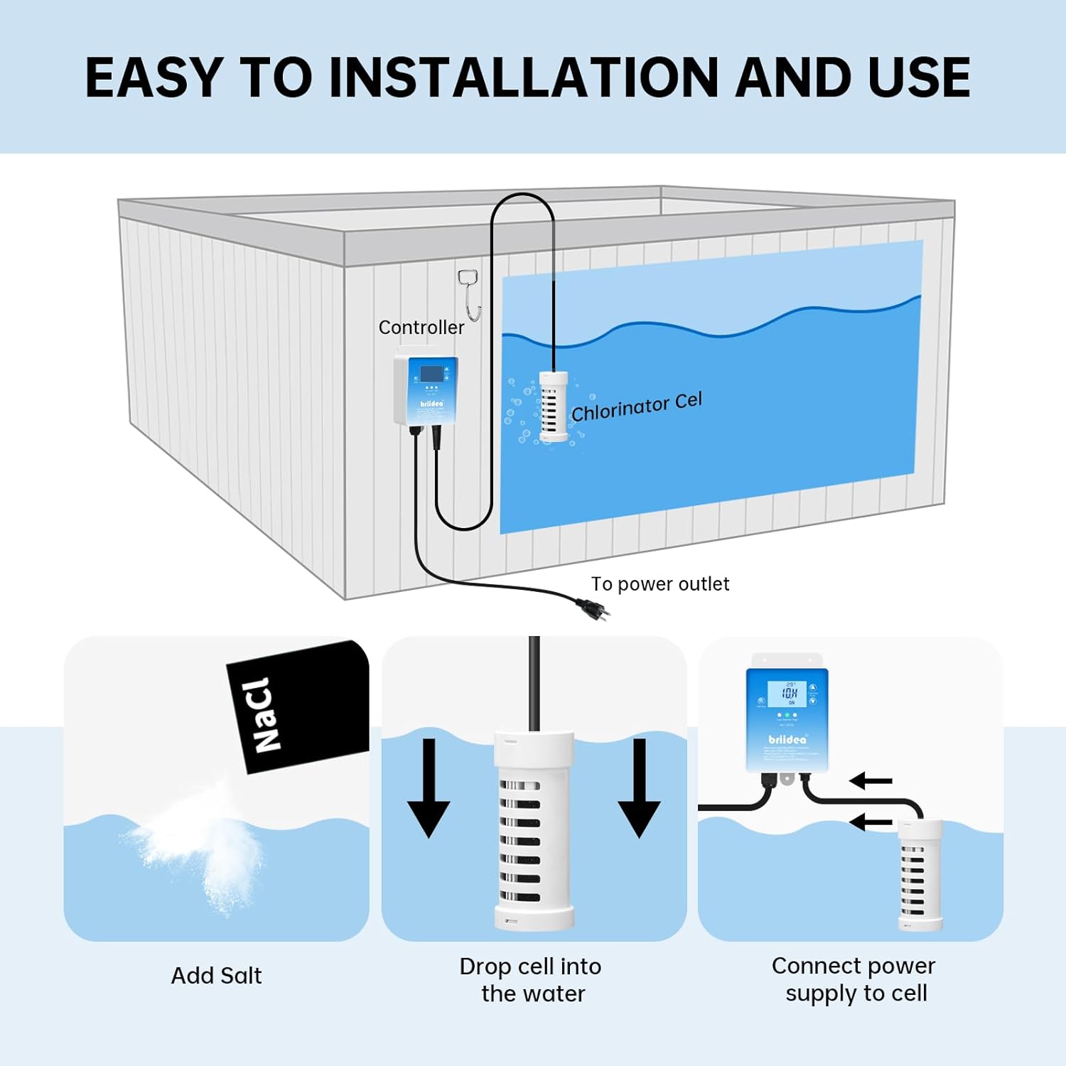
Figure 2: Diagram illustrating the simple installation process of the controller and chlorinator cell.
6. Operation
The BR-159 features a built-in timer/controller for automated operation. Once installed and powered on, the unit will begin to generate chlorine.
- LED Indicators: The controller's LED display shows the water temperature and the current operating status. The "Salt Level" indicators (Low, Normal, High) provide a quick visual reference for your spa's salinity.
- Setting the Timer: Use the controls on the unit (or a connected app if available for your model) to set the daily operating time. The optimal run time will vary based on spa size, usage, and desired chlorine levels. Start with a recommended duration (e.g., 3-4 hours for a typical hot tub) and adjust as needed based on water testing.
- Salt Concentration Detection: The device continuously monitors the salt level. If the salt level is too low, the unit may reduce or stop chlorine production. If too high, it may indicate a need to dilute the water.
- Chlorine Production: The chlorinator cell converts salt into chlorine, which sanitizes the water. You may observe small bubbles emanating from the cell during operation, indicating active chlorine generation.
Video 1: Demonstration of the Briidea Salt Chlorine Generator's display and the chlorinator cell actively producing chlorine in a hot tub. The video shows the unit's interface displaying temperature and operating status, followed by a close-up of the cell releasing small bubbles into the water.
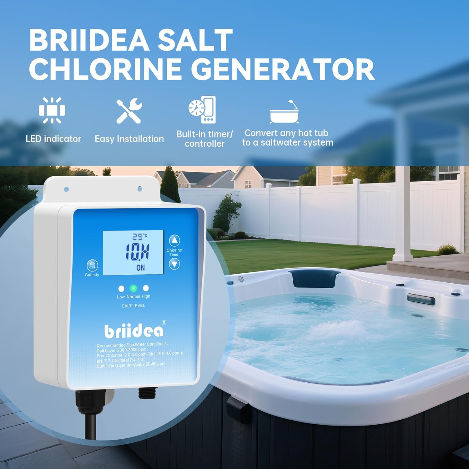
Figure 3: The Briidea BR-159 Salt Chlorine Generator controller mounted above a hot tub, showing its LED display and key features.
7. Maintenance
Regular maintenance ensures the longevity and efficiency of your salt chlorine generator.
- Water Chemistry Monitoring: Regularly test your spa water for chlorine levels, pH, and alkalinity. Adjust the generator's run time or add balancing chemicals as needed to maintain recommended levels. Recommended spa water conditions: Salt Level: 2000-3000 ppm, Free Chlorine: 2.0-4.0 ppm (ideal 3.0-4.0 ppm), pH: 7.2-7.8, Alkalinity: 80-120 ppm, Stabilizer (Cyanuric Acid): 50-80 ppm.
- Cell Cleaning: The titanium electrodes are designed for long-term performance (up to 3,000 hours) and feature polarity reversal to minimize scale buildup. However, periodic inspection and cleaning of the cell may be necessary, especially in hard water areas.
- Disconnect power to the unit.
- Remove the chlorinator cell from the water.
- Inspect for scale buildup (white, flaky deposits) on the electrodes.
- If buildup is present, soak the cell in a mild acid solution (e.g., diluted muriatic acid or a commercial cell cleaning solution) according to the solution's instructions. Do not scrape the electrodes with metal objects.
- Rinse thoroughly with fresh water before re-installing.
- Salt Level Management: The unit's salt concentration detection helps you monitor salinity. Add salt if the indicator shows "Low" or if water tests confirm low levels. If the indicator shows "High," partially drain and refill the spa with fresh water to dilute the salt concentration.
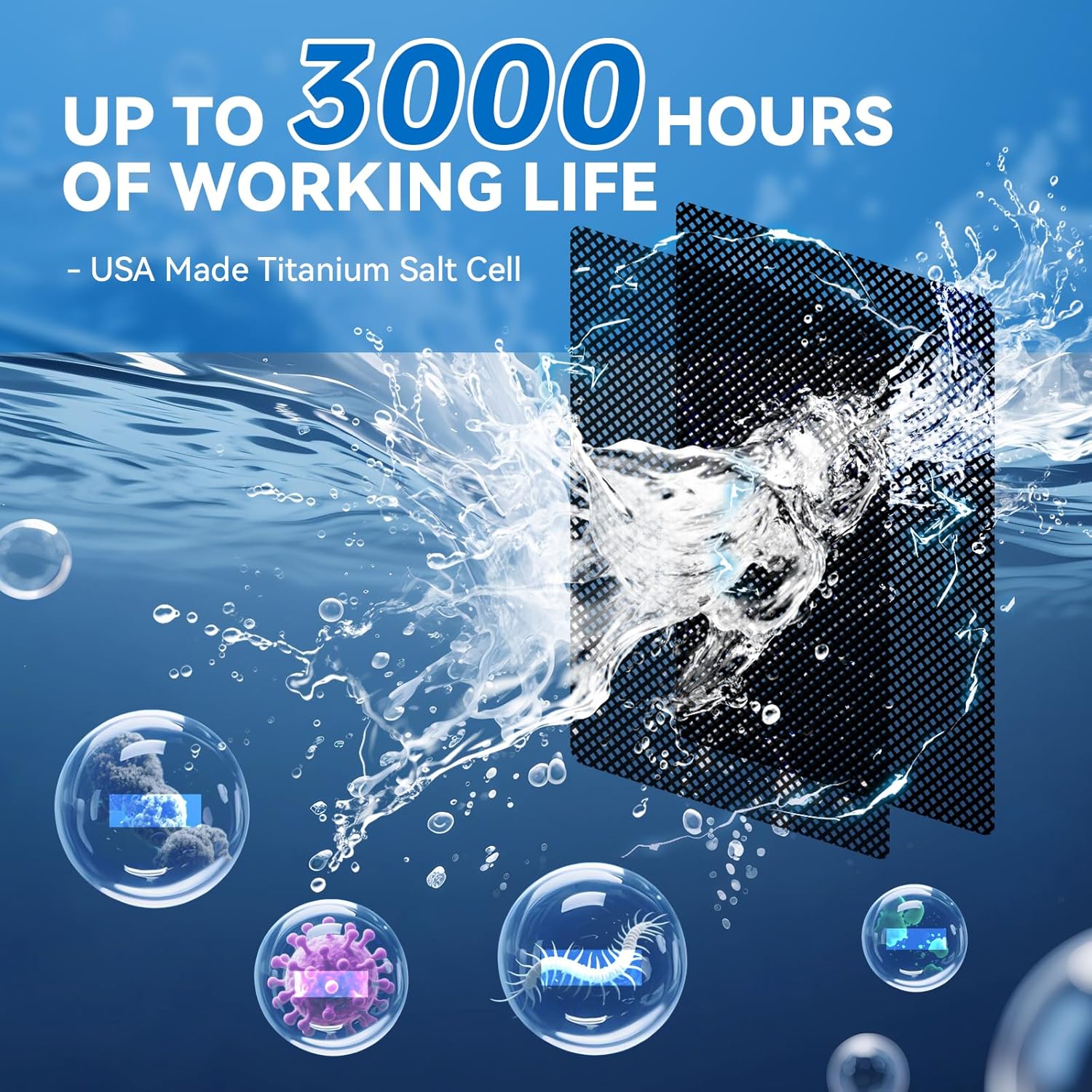
Figure 4: Illustration highlighting the USA-made titanium electrodes within the chlorinator cell, designed for durability and efficient chlorine production.
8. Troubleshooting
Refer to this section for common issues and their solutions.
| Problem | Possible Cause | Solution |
|---|---|---|
| No chlorine production | Low salt level, dirty cell, power issue, insufficient run time. | Check salt level and add salt if needed. Clean the chlorinator cell. Ensure unit is powered on and connected correctly. Increase daily run time. |
| "Low Salt" indicator on | Actual low salt concentration, sensor issue. | Test water salinity with a separate kit. Add salt gradually and allow it to dissolve. If salt level is correct, contact support. |
| "High Salt" indicator on | Actual high salt concentration, sensor issue. | Partially drain spa and refill with fresh water to dilute. Test salinity. If salt level is correct, contact support. |
| Controller display is off | No power, loose connection. | Check power outlet and connections. Ensure GFCI has not tripped. |
9. Warranty and Support
For warranty information or technical support, please contact Briidea customer service. Keep your purchase receipt as proof of purchase for any warranty claims.
Contact information can typically be found on the Briidea official website or on your product packaging.


