
1. Introduction
The Aramox SUL181D is a 24-hour mechanical timer designed for precise control of electrical devices. It functions as a switch relay, capable of handling 250VAC at 16A, making it suitable for a wide range of applications including industrial control, street lighting, farm equipment, and various home appliances. This timer features a robust design with high-temperature and fireproof thermoplastic materials, ensuring durability and safety. Its compact size and simple structure facilitate easy installation and operation.
2. Safety Information
- Always disconnect power before installation, maintenance, or any wiring adjustments to prevent electrical shock.
- Installation should be performed by a qualified electrician in accordance with local electrical codes and regulations.
- Ensure the timer's electrical ratings (voltage, current) are compatible with the connected load.
- Do not expose the timer to moisture or extreme temperatures outside its specified operating range.
- Verify all connections are secure to prevent loose wiring and potential hazards.
3. Product Overview
The SUL181D mechanical timer consists of a time dial, setting segments, a manual override switch, and a terminal block for electrical connections. The clear cover protects the dial and settings while allowing visibility.

Figure 3.1: Angled view of the SUL181D Mechanical Timer, highlighting its main components including the time dial and terminal connections.
Key Components:
- Time Dial: A 24-hour rotating dial used to set the current time and program ON/OFF periods.
- Setting Segments: Small blue segments around the dial that are pushed in or pulled out to define ON/OFF intervals. Each segment typically represents 15 minutes.
- Manual Override Switch: Allows for temporary manual control of the connected device, overriding the programmed schedule.
- Terminal Block: Located at the bottom, used for connecting power input (L, N) and load output (1, 2, 3).
- DIN Rail Clip: Located on the back for easy mounting onto a DIN rail.
4. Specifications
| Feature | Specification |
|---|---|
| Model | SUL181D (Aramoxx60reg1pvn) |
| Rated Voltage | 250VAC |
| Rated Current | 16A |
| Coil Power | 0.2W (230VAC) |
| Switching Current | 16A |
| Switching Voltage | 250VAC |
| Time Range | 24 hours |
| Minimum Switching Time | 15 minutes |
| Number of Switching Sections | 96 (15-minute intervals) |
| Power Storage Time (after power failure) | Approx. 100 hours at 110V |
| Frequency | 50 ~ 60 Hz |
| Installation Form | DIN rail |
| Terminal Block Form | Plug-in terminal |
| Dimensions (L x W x H) | 4.72 x 3.15 x 2.36 inches (120 x 80 x 60 mm) |
| Item Weight | 5 ounces (142 grams) |
| Ambient Temperature | -20 ℃ ~ +55 ℃ |
5. Installation
5.1 Mounting
The SUL181D timer is designed for DIN rail mounting. Locate a suitable DIN rail within your electrical enclosure. Align the timer's DIN rail clip with the rail and press firmly until it clicks into place. Ensure the timer is securely fastened.

Figure 5.1: Side view illustrating the DIN rail mounting mechanism.
5.2 Wiring
Refer to the wiring diagram on the timer and the image below for correct connections. Always ensure power is disconnected before wiring.
- L (Line): Connect the live (phase) wire of your power supply to the 'L' terminal.
- N (Neutral): Connect the neutral wire of your power supply to the 'N' terminal.
- 1 (Common): This is the common terminal for the switch output.
- 2 (Normally Open - NO): Connect one side of your load to this terminal if you want the load to turn ON when the timer is active.
- 3 (Normally Closed - NC): Connect one side of your load to this terminal if you want the load to turn OFF when the timer is active.
- Connect the other side of your load to the neutral (N) wire of your power supply.

Figure 5.2: Front view detailing the terminal block for electrical connections.
6. Operating Instructions
6.1 Setting the Current Time
- Rotate the entire 24-hour dial clockwise until the current time aligns with the small arrow or marker on the inner fixed part of the timer.
- Ensure the AM/PM distinction is correctly observed (e.g., 1 PM is 13:00, 6 PM is 18:00).
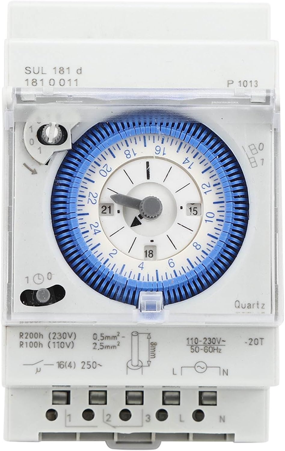
Figure 6.1: Close-up of the time dial, showing the 24-hour scale and individual setting segments.
6.2 Programming ON/OFF Periods
The blue segments around the dial control the ON/OFF periods. Each segment represents 15 minutes.
- To set an ON period: Push the segments corresponding to the desired ON time inwards towards the center of the dial.
- To set an OFF period: Pull the segments corresponding to the desired OFF time outwards away from the center of the dial.
- You can program up to 96 ON/OFF events within a 24-hour cycle.
6.3 Manual Override
The timer includes a manual override switch, typically a small lever or button, which allows you to temporarily bypass the programmed schedule.
- Locate the manual override switch, usually near the time dial.
- Move the switch to the desired position (e.g., 'ON' or 'OFF') to manually control the load.
- To return to automatic operation, move the switch back to the 'AUTO' or timer symbol position.

Figure 6.2: View with the protective cover open, showing the manual override switch for temporary control.
7. Maintenance
- Cleaning: Periodically wipe the exterior of the timer with a soft, dry cloth. Do not use abrasive cleaners or solvents. Ensure no liquids enter the timer's housing.
- Inspection: Regularly check for any signs of damage, loose connections, or overheating. If any issues are observed, disconnect power and consult a qualified technician.
- Battery Backup: The timer has a power storage function (approx. 100 hours) to maintain time settings during power outages. No user maintenance is required for this feature.
8. Troubleshooting
- Timer not operating:
- Check if the power supply is connected correctly to the 'L' and 'N' terminals and is active.
- Ensure the manual override switch is in the 'AUTO' or timer symbol position.
- Verify the current time is set correctly.
- Load not switching ON/OFF as programmed:
- Confirm that the setting segments for the desired ON/OFF times are correctly pushed in or pulled out.
- Check the wiring to the load (terminals 1, 2, 3) for secure connections and correct configuration (Normally Open/Normally Closed).
- Ensure the load itself is functional and not drawing excessive current that could trip a circuit breaker.
- Inaccurate timing:
- Verify the current time is set accurately.
- The timer has a time accuracy of ≤ ± 1 s / day (quartz). Significant deviations may indicate a fault.
9. Warranty and Support
For warranty information or technical support, please refer to the product packaging or contact the retailer or manufacturer directly. Keep your purchase receipt as proof of purchase.