1. Introduction
This manual provides detailed instructions for the installation, operation, and maintenance of the 5MNG0Y8 AT4PW 100A Din Rail Smart Switch. This device is designed to measure and display various electrical parameters including voltage, current, power, energy (kWh), frequency, and power factor. It also features remote control capabilities via WiFi, allowing for smart management of electrical circuits.
Please read this manual thoroughly before installation and operation to ensure safe and correct usage.
2. Safety Information
Warning: Electrical installation and wiring should only be performed by qualified personnel. Failure to follow these instructions may result in electric shock, fire, or serious injury.
- Ensure power is disconnected before any installation or wiring.
- Do not operate the device in wet or damp conditions.
- Verify correct wiring connections to prevent damage to the device or connected equipment.
- Do not exceed the maximum rated current of 100A.
3. Product Overview
The AT4PW is a compact Din rail mounted smart switch and energy meter. It features a 2.4-inch TFT-LCD HD display panel for clear visualization of electrical data and supports WiFi connectivity for remote monitoring and control.
3.1 Components
- Display Panel: 2.4 inches TFT-LCD HD Display Panel Graphic 240*320 RGB Dot-matrix.
- Input Terminals: L-IN (Live Input), N-IN (Neutral Input).
- Output Terminals: L-OUT (Live Output), N-OUT (Neutral Output).
- Control Buttons: For navigation and settings.
- Din Rail Clip: For mounting on a standard 35mm Din rail.
3.2 Product Views
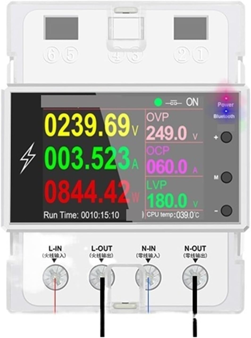
Figure 1: Front view of the AT4PW Din Rail Smart Switch. The LCD display shows real-time voltage, current, power, energy, frequency, and power factor readings. Indicators for Power, Bluetooth, and WiFi are visible on the right side of the display.

Figure 2: Bottom view of the AT4PW Din Rail Smart Switch, illustrating the L-IN, N-IN, L-OUT, and N-OUT terminals for electrical connections. The device is shown mounted on a standard Din rail.
4. Installation
The AT4PW is designed for 35mm Din rail installation.
- Power Disconnection: Before starting, ensure that the main power supply to the circuit where the device will be installed is completely disconnected. Use appropriate lockout/tagout procedures.
- Mounting: Clip the AT4PW device onto a standard 35mm Din rail in your electrical distribution box or panel. Ensure it is securely fastened.
- Wiring:
- Connect the incoming Live wire to the L-IN terminal.
- Connect the incoming Neutral wire to the N-IN terminal.
- Connect the outgoing Live wire (to the load) to the L-OUT terminal.
- Connect the outgoing Neutral wire (to the load) to the N-OUT terminal.
Refer to Figure 2 for terminal identification. Ensure all connections are tight and secure.
- Power Restoration: Once all wiring is complete and verified, restore power to the circuit. The device display should illuminate.
5. Setup and Configuration
5.1 Initial Power-On
Upon first power-on, the device will display the main measurement interface. You may need to set the date, time, and other regional settings if prompted.
5.2 WiFi Connection
To enable remote control and monitoring, connect the device to your WiFi network.
- Download App: Scan the QR code (if provided on the device or packaging) or search for the designated smart home app (e.g., Tuya Smart, Smart Life) on your smartphone's app store.
- Register/Login: Create an account or log in to the app.
- Add Device: In the app, select "Add Device" or the "+" icon. Choose "Electrical" or "Switch" category, then select the specific device type (e.g., "Din Rail Switch" or "Energy Meter").
- Pairing Mode: Follow the app's instructions to put the AT4PW into pairing mode. This usually involves pressing and holding a button on the device until a WiFi indicator blinks rapidly.
- Connect to WiFi: Enter your WiFi network name (SSID) and password in the app. Ensure your phone is connected to the same 2.4GHz WiFi network.
- Completion: Once connected, the WiFi indicator on the device will become solid, and the device will appear in your app.
6. Operating Instructions
6.1 Local Operation
- Display Navigation: Use the physical buttons on the device (if present) to cycle through different display screens, showing various parameters like voltage, current, power, energy, frequency, and power factor.
- Switch Control: The device may have a physical button to manually turn the connected load ON/OFF.
6.2 Remote Operation (via App)
Once connected to the app, you can perform the following functions remotely:
- ON/OFF Control: Remotely switch the connected load on or off.
- Real-time Monitoring: View real-time electrical parameters (voltage, current, power, etc.) from anywhere.
- Energy Consumption Tracking: Monitor daily, weekly, or monthly energy consumption (kWh).
- Scheduling: Set schedules or timers for automatic ON/OFF operations.
- Automation: Create smart scenes or automations based on conditions (e.g., turn off if power exceeds a limit).
7. Maintenance
- Cleaning: Use a soft, dry cloth to clean the device. Do not use abrasive cleaners or solvents.
- Firmware Updates: Periodically check the mobile app for available firmware updates for the device to ensure optimal performance and security.
- Connection Check: Occasionally check wiring connections for tightness, especially after initial installation or if any issues arise.
8. Troubleshooting
| Problem | Possible Cause | Solution |
|---|---|---|
| Device display is off. | No power supply; incorrect wiring. | Check main power supply. Verify L-IN and N-IN connections. |
| Cannot connect to WiFi. | Incorrect WiFi password; 5GHz network; device not in pairing mode; weak signal. | Ensure correct 2.4GHz WiFi password. Put device into pairing mode. Move device closer to router. |
| Remote control not working. | No internet connection; device offline; app issue. | Check home internet connection. Verify device is online in the app. Restart app or device. |
| Inaccurate readings. | Loose wiring; device malfunction. | Check all wiring connections for tightness. If issue persists, contact support. |
9. Specifications
| Parameter | Value |
|---|---|
| Model Number | AT4PW |
| Rated Voltage | AC 85-265V (Input/Output) |
| Max Operating Current | 100A |
| Accuracy Class | 1% |
| Measuring Energy Range | 0-99999 kWh |
| Power Range | Max 26.5KW |
| Display Type | 2.4 inches TFT-LCD HD Display Panel Graphic 240*320 RGB Dot-matrix |
| Installation | 35mm Din rail |
| Operating Temperature | -20°C ~ +60°C |
| Dimensions | 76*76*97mm |
| Connectivity | WiFi |
| Certification | CE, RoHS |
10. Warranty and Support
For warranty information and technical support, please refer to the documentation included with your purchase or contact the manufacturer directly. Keep your purchase receipt as proof of purchase.
Manufacturer: 5MNG0Y8
For further assistance, please visit the official 5MNG0Y8 website or contact their customer service.