1. Introduction
This manual provides detailed instructions for the safe and effective operation of your TOOLTOP ET120M 120MHz Handheld Digital Oscilloscope. Please read this manual thoroughly before using the device to ensure proper functionality and to prevent damage.
2. Safety Information
Always observe the following safety precautions when using the ET120M oscilloscope:
- Do not operate the device in wet or damp conditions.
- Ensure the device is powered off before connecting or disconnecting probes.
- Use only the provided accessories or approved replacements.
- Do not attempt to open or modify the device; refer all servicing to qualified personnel.
- Keep the device away from strong electromagnetic fields.
3. Package Contents
Verify that all items listed below are present in your package:
- TOOLTOP ET120M Handheld Digital Oscilloscope
- 100MHz Oscilloscope Probe
- USB Charging Cable
- User Manual
- Cloth Bag

Figure 3.1: Package Contents
4. Product Overview
4.1. Device Features
The TOOLTOP ET120M is a compact and portable handheld digital oscilloscope designed for various electrical testing and repair applications. Key features include:
- 120MHz analog bandwidth and 500MS/s real-time sampling rate.
- 2.4-inch 320x240 clear color LCD screen.
- Integrated square wave signal output (1kHz, 10KHz, 100KHz, 1MHz).
- 12 types of automatic parameter measurements (Vpp, Vrms, Vavg, Vp, Vmax, Vmin, F, T, T+, T-, Du+, Du-).
- Three scan modes: Auto, Normal, and Single.
- Ability to store 2500 DSO waveforms with thumbnail browsing.
- Built-in rechargeable lithium battery for up to 6 hours of continuous use.
- Durable design with a silicone protective cover.

Figure 4.1: Key Features Overview
4.2. Component Identification
Familiarize yourself with the main components and controls of the ET120M oscilloscope:

Figure 4.2: Front View of ET120M Oscilloscope
- Display Screen: 2.4-inch LCD for waveform display and menu navigation.
- Input BNC Connector: For connecting the oscilloscope probe.
- Control Buttons: Including MENU, F1, F2, SAVE, AC/DC, 1X/10X, 50%, TRIG, EDGE, STOP, AUTO, and directional/OK buttons for navigation and settings adjustment.
- USB Port: For charging the device.
5. Setup
5.1. Initial Charging
Before first use, fully charge the built-in lithium battery using the provided USB charging cable and a standard USB power adapter (not included). The charging indicator will show the charging status.
5.2. Probe Connection
Connect the oscilloscope probe to the BNC input connector on the top of the device. Ensure the connection is secure. Set the probe attenuation switch (if applicable) to the desired setting (e.g., 1X or 10X) and match this setting on the oscilloscope via the 1X/10X button.
6. Operating Instructions
6.1. Power On/Off
Press and hold the power button (usually located on the side or top) to turn the device on or off.
6.2. Basic Waveform Acquisition
After powering on, connect the probe to the circuit under test. The oscilloscope will display the waveform. Use the directional buttons to navigate menus and adjust settings.
6.3. Waveform Acquisition Modes
The ET120M supports three scan modes:
- Auto: Automatically adjusts time base and vertical amplitude for a stable waveform display. Press the AUTO button for one-key waveform adaptation.
- Normal: Displays a waveform only when a trigger condition is met.
- Single: Captures and displays a single waveform when a trigger condition is met, then stops.

Figure 6.1: Auto Waveform Adaptation
6.4. Parameter Measurement
The device can automatically measure 12 different waveform parameters. Access these measurements through the menu system. Parameters include Peak-to-Peak Voltage (Vpp), Root Mean Square Voltage (Vrms), Average Voltage (Vavg), Peak Voltage (Vp), Maximum Voltage (Vmax), Minimum Voltage (Vmin), Frequency (F), Period (T), Positive Pulse Width (T+), Negative Pulse Width (T-), Positive Duty Cycle (Du+), and Negative Duty Cycle (Du-).
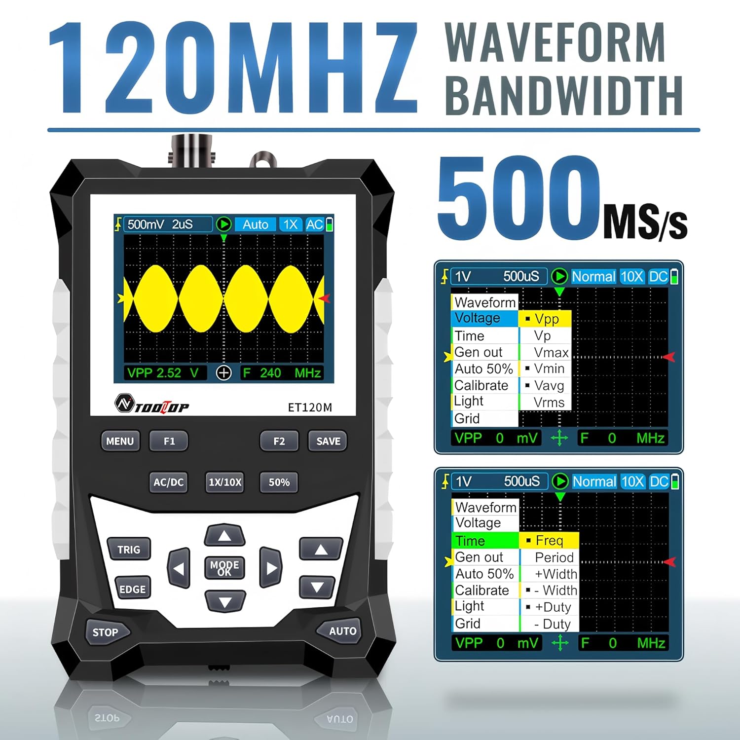
Figure 6.2: Automatic Measurement Functions
6.5. Square Wave Signal Output
The ET120M can generate square wave signals at specific frequencies. Navigate to the signal output function in the menu to select between 1kHz, 10KHz, 100KHz, and 1MHz output frequencies. This feature is useful for testing circuits.

Figure 6.3: Square Wave Signal Output Function
6.6. Waveform Storage and Recall
The device can store up to 2500 DSO waveforms. Use the SAVE button to store the current waveform. Stored waveforms can be browsed via thumbnails for easy recall and analysis.

Figure 6.4: Waveform Storage and Browsing
6.7. Adjusting Waveform Parameters
You can manually adjust various waveform display parameters to fine-tune your measurements:
- Time Base: Adjusts the horizontal scale (time per division).
- Amplitude (Vertical Sensitivity): Adjusts the vertical scale (volts per division).
- Trigger Slope: Sets the trigger to rising or falling edge.
- Trigger Level: Sets the voltage level at which the waveform is triggered.

Figure 6.5: Adjusting Waveform Display Parameters
7. Maintenance
7.1. Cleaning
To clean the device, use a soft, dry cloth. For stubborn dirt, a slightly damp cloth with mild detergent can be used, ensuring no liquid enters the device. Do not use abrasive cleaners or solvents.
7.2. Storage
When not in use for extended periods, store the oscilloscope in a cool, dry place, away from direct sunlight and extreme temperatures. It is recommended to store it in the provided cloth bag to protect it from dust and scratches.
7.3. Battery Care
To prolong battery life, avoid fully discharging the battery frequently. If storing for a long time, charge the battery to approximately 50% every few months.
8. Troubleshooting
If you encounter issues with your ET120M oscilloscope, refer to the following common problems and solutions:
- Device does not power on: Ensure the battery is charged. Connect the USB charging cable and try again.
- No waveform displayed: Check probe connection. Ensure the probe is properly connected to the circuit under test. Adjust vertical sensitivity and time base settings. Try the AUTO function.
- Unstable waveform: Adjust the trigger level and trigger slope. Ensure the trigger mode is appropriate for the signal.
- Inaccurate measurements: Verify probe attenuation setting (1X/10X) matches the device setting. Perform a probe compensation if necessary (refer to advanced operation in a full manual).
For persistent issues, contact TOOLTOP customer support.
9. Specifications
9.1. General Specifications
| Display | 320x240 LCD screen |
| Display Area | 50mm x 40mm |
| Backlight | White, brightness adjustable |
| Impedance | x1: 1MΩ / x10: 10MΩ |
| Battery | 18650 lithium battery (built-in) |
| Auto Shutdown | No operation for 15 minutes |
| Waveform Storage | 2500 DSO waveforms |
| Size | 124mm x 80mm x 35mm |
| Operating Conditions | 0°C ~ +40°C; <75%RH |
| Storage Conditions | -10°C ~ +60°C; <90%RH |
9.2. Oscilloscope Specifications
| Analog Bandwidth | 120MHz |
| Maximum Real-time Sampling Rate | 500MSps |
| Vertical Resolution | 8 bits |
| Vertical Accuracy | ±(5% + 0.2div) |
| Auto Zero Reference | During DC measurement |
| Trigger Level | ±3.8div (0.1div per step) |
| Trigger Position | ±6div (0.1div per step) |
| Cursor Function | ΔV, Δt, 1/Δt |
| Nonlinearity | ±1 bits |
| Coupling Method | DC/AC |
| Division Vertical | ±3.8 Horizontal: 12 |
| Time Base Range | 6ns/div ~ 50s/div |
| Time Base Accuracy | ±(0.01%+0.1div) |
| Scan Mode | Auto/Single/Normal |
| Trigger Slope | Rising / Falling |
| Record Length | 12div |
| Auto Configuration | Automatically set time base and vertical amplitude |
| Automatic Measurement Functions | Vpp, Vrms, Vavg, Vp, Vmax, Vmin, F, T, T+, T-, Du+, Du- |
| Vertical Sensitivity Range | x1: 50mV/div ~ 10V/div; x10: 500mV/div ~ 100V/div |
10. Warranty and Support
For warranty information or technical support, please refer to the documentation provided with your purchase or contact TOOLTOP customer service directly. Keep your purchase receipt as proof of purchase.


