1. Introduction
The DALY 24V 8S 150A Smart Battery Management System (BMS) with 1A Active Balancer is designed to provide comprehensive protection and efficient management for 8-series 24-volt LiFePO4 battery packs. This system ensures the longevity and optimal performance of your battery by monitoring and controlling various parameters. It is suitable for applications such as mobility scooters, electric wheelchairs, RVs, marine setups, and other portable power solutions.
Key features include low voltage cutoff, high voltage cutoff, short circuit protection, and temperature protection. The integrated Bluetooth/Wi-Fi module allows for convenient local and remote monitoring via a dedicated mobile application, providing real-time system alerts and customizable parameters.
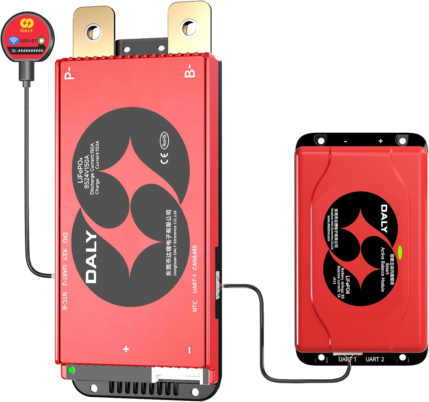
Image 1.1: DALY 24V 8S 150A Smart BMS and 1A Active Balancer components.
2. Safety Information
Please read all safety instructions carefully before installation and operation. Failure to follow these instructions may result in electric shock, fire, or serious injury.
- Professional Installation Recommended: Installation should be performed by qualified personnel with knowledge of electrical systems and battery safety.
- Wear Protective Gear: Always wear insulated gloves and eye protection when working with batteries and electrical components.
- Disconnect Power: Ensure all power sources are disconnected before installing or servicing the BMS.
- Correct Polarity: Verify correct polarity of all connections (positive to positive, negative to negative) to prevent damage to the BMS and battery pack.
- Avoid Short Circuits: Do not allow tools or metal objects to bridge battery terminals or BMS connections.
- Ventilation: Ensure adequate ventilation around the battery pack and BMS to prevent heat buildup.
- Temperature Limits: Operate the BMS and battery within specified temperature ranges.
- Emergency Procedures: Familiarize yourself with emergency shutdown procedures for your battery system.
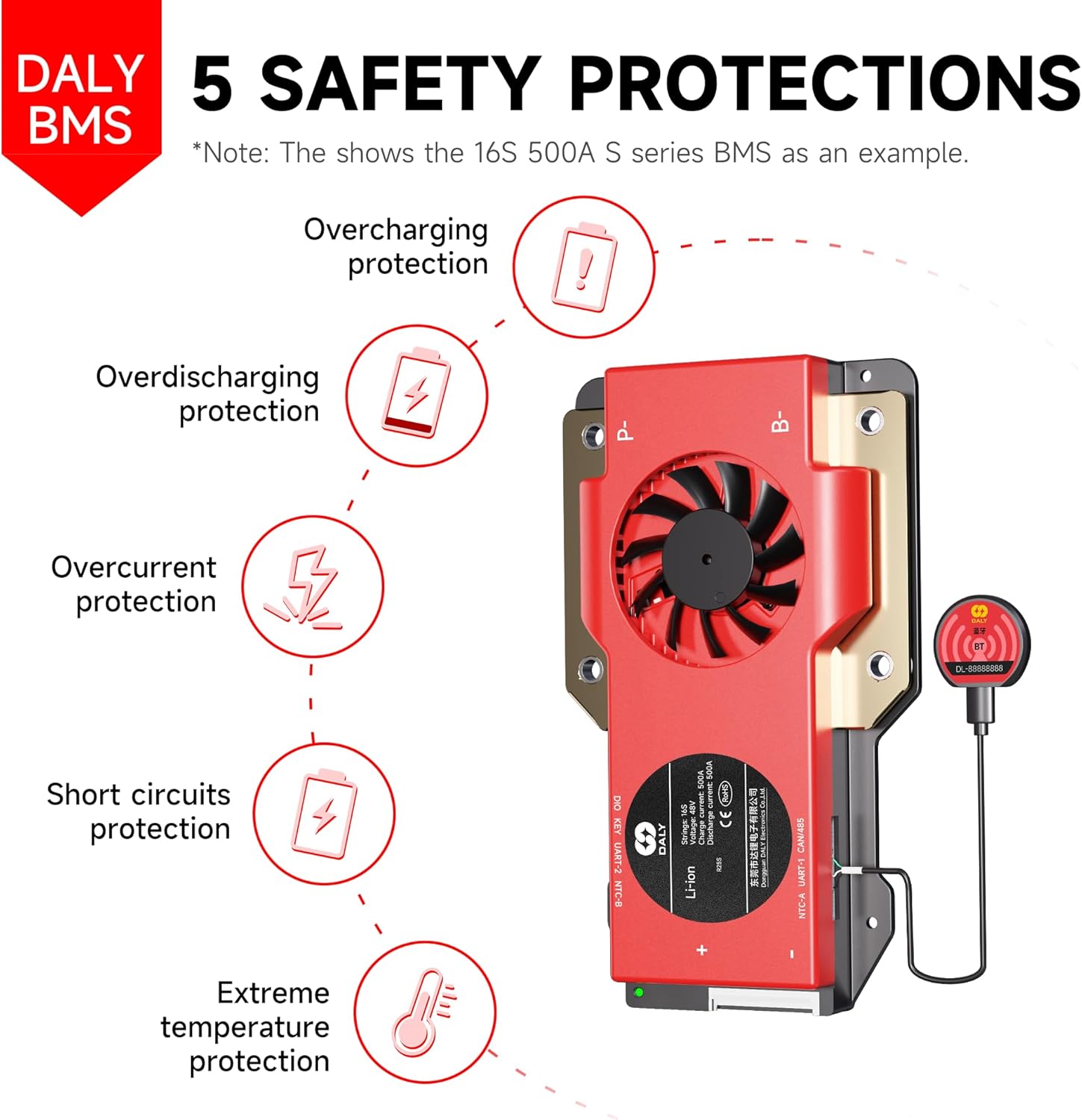
Image 2.1: DALY BMS provides 5 safety protections: Overcharging, Overdischarging, Overcurrent, Short Circuit, and Extreme Temperature protection.
3. Package Contents
Please verify that all items listed below are included in your package:
- 8S 24V 150 Amps Smart BMS ×1
- 1A 8S Smart Active Balancer ×1
- B-P-Output line ×1
- 2-in-1 BT/WiFi dongle ×1
- Sampling cable ×1
- NTC (Temperature Sensor) ×1
- Instruction Manual ×1
- Screws (for mounting)
- CAN/485 5pin cable (if applicable to your model)

Image 3.1: Illustrated packing list for the DALY BMS system.
4. Setup and Installation
Follow these steps for proper installation of your DALY Smart BMS and Active Balancer:
- Prepare the Battery Pack: Ensure your 8S LiFePO4 battery pack is assembled and all cells are at a similar state of charge.
- Connect the Sampling Cable: Carefully connect the multi-pin sampling cable to the BMS. Ensure the first wire (B0) is connected to the negative terminal of the first cell, and subsequent wires are connected to the positive terminals of each cell in series (B1, B2, ..., B8). The last wire (B8) connects to the positive terminal of the last cell.
- Connect the Active Balancer: Connect the 1A Active Balancer to the designated port on the Smart BMS.
- Connect the B-P-Output Line: Connect the B- wire from the BMS to the main negative terminal of the battery pack. Connect the P- wire from the BMS to the negative terminal of your load/charger.
- Connect the NTC (Temperature Sensor): Attach the NTC sensor to a central cell or a location that accurately reflects the battery pack's temperature. Connect the NTC cable to the BMS.
- Connect the Bluetooth/Wi-Fi Dongle: Plug the 2-in-1 BT/WiFi dongle into the communication port on the BMS.
- Final Check: Double-check all connections for correctness and security before applying power.
Important: Using a mismatched BMS (e.g., incorrect voltage or current rating for your battery pack) can severely damage your battery and potentially cause hazards. Refer to the specifications and consult the manufacturer if unsure about compatibility.

Image 4.1: Example of a DALY BMS connected to a battery pack, demonstrating support for multiple parallel systems to increase capacity.
5. Operating Instructions
5.1. Smart BMS Mobile Application
The DALY Smart BMS can be monitored and configured via a mobile application using the included 2-in-1 Bluetooth/Wi-Fi dongle.
- Download the App: Search for the 'Smart BMS' app on your smartphone's app store (iOS or Android).
- Connect via Bluetooth/Wi-Fi: Ensure the dongle is connected to the BMS. Open the app and follow the on-screen instructions to connect to your BMS via Bluetooth for local monitoring or Wi-Fi for remote access.
- Monitor Parameters: The app displays real-time data such as battery voltage, current, individual cell voltages, temperature, state of charge (SOC), and protection status.
- Customize Settings: Access advanced settings to adjust protection parameters, balancing thresholds, and other operational characteristics.
- Receive Alerts: The app provides real-time alerts for any abnormal conditions detected by the BMS.
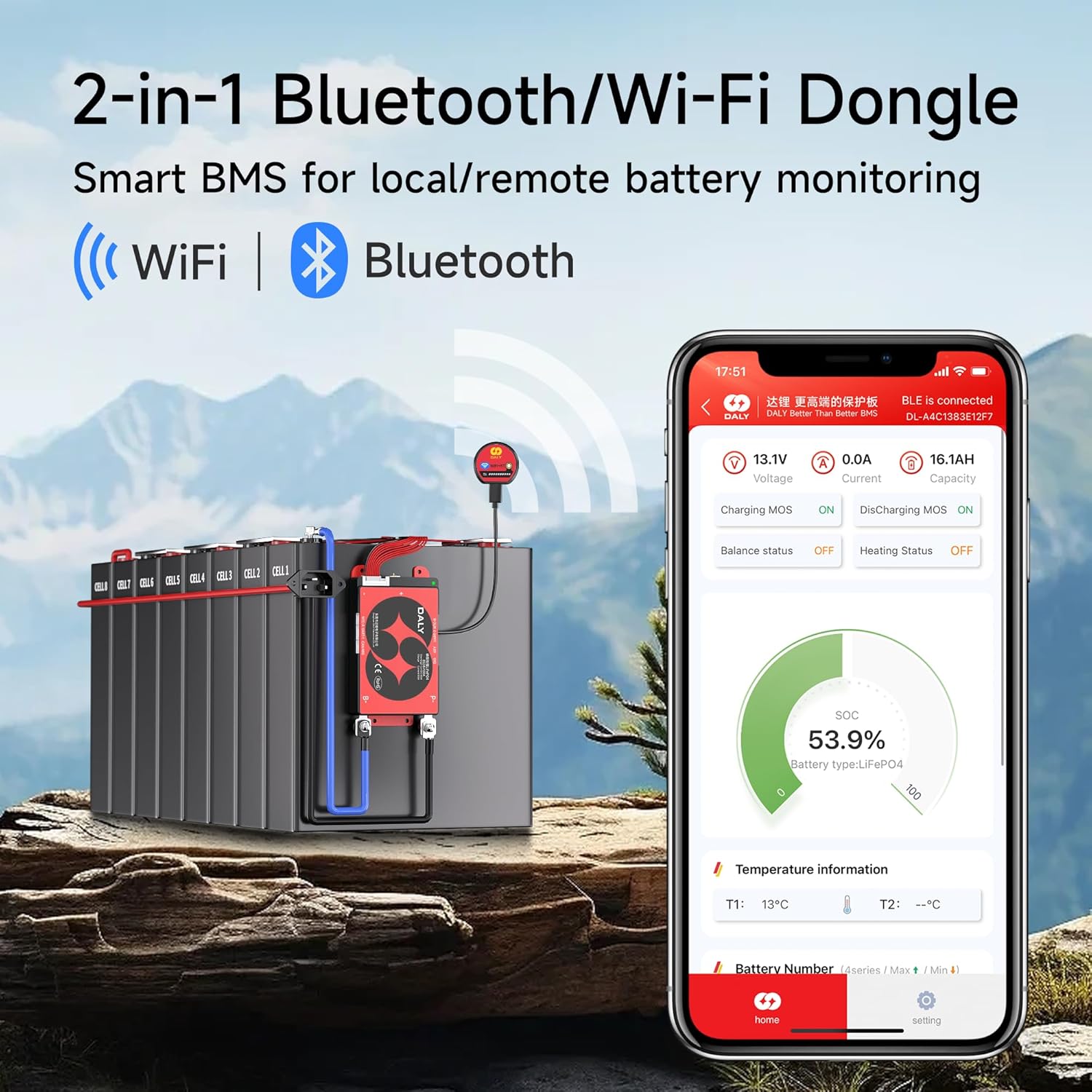
Image 5.1: The Smart BMS mobile application displaying real-time battery monitoring data and connection status.
5.2. Active Cell Balancing
The 1A Smart Active Balancer works in conjunction with the BMS to ensure all cells in your battery pack maintain a balanced voltage. This process is crucial for maximizing battery capacity, extending lifespan, and preventing damage from overcharging or over-discharging individual cells.
- The active balancer automatically detects voltage differences between cells.
- It transfers energy from higher-voltage cells to lower-voltage cells, achieving faster and more efficient balancing compared to passive balancing.
- This process generates less heat and improves overall energy efficiency of the battery system.

Image 5.2: Active cell balancing process, managed through a single application for simplified control.
5.3. Parallel System Support
The DALY Smart BMS features a built-in current limiting module that supports multiple parallel battery systems. This allows you to easily scale up your battery capacity and runtime by connecting additional battery packs equipped with DALY BMS units.
- Connect multiple battery packs in parallel according to your system design.
- The BMS manages the current flow and protection across the entire parallel system.
6. Maintenance
To ensure optimal performance and longevity of your DALY Smart BMS and battery pack, follow these maintenance guidelines:
- Regular Inspection: Periodically inspect all wiring and connections for signs of wear, corrosion, or looseness. Tighten any loose connections.
- Cleanliness: Keep the BMS and battery pack clean and free from dust, dirt, and moisture. Use a dry, soft cloth for cleaning.
- Environmental Conditions: Ensure the BMS and battery are operated within their specified temperature and humidity ranges. Avoid extreme heat, cold, or direct sunlight.
- Software Updates: Check for and install any available firmware or app updates for your Smart BMS to ensure you have the latest features and bug fixes.
- Battery Health Monitoring: Regularly check battery health parameters via the mobile app. Address any persistent warnings or abnormal readings promptly.
7. Troubleshooting
This section addresses common issues you might encounter with your DALY Smart BMS.
7.1. BMS Not Powering On / No Output
- Check Main Connections: Verify that the B- and P- wires are correctly and securely connected.
- Check Sampling Cable: Ensure the sampling cable is fully inserted and all individual cell wires are correctly connected to their respective cell terminals. A loose or incorrect connection can prevent the BMS from operating.
- Battery Voltage: Confirm that the overall battery pack voltage is within the operational range of the BMS.
7.2. App Connection Issues (Bluetooth/Wi-Fi)
- Dongle Connection: Ensure the 2-in-1 BT/WiFi dongle is securely plugged into the BMS communication port.
- Power Cycle: Try power cycling the BMS (disconnect and reconnect the main battery power) and restart the app.
- Device Proximity: For Bluetooth, ensure your smartphone is close to the BMS. For Wi-Fi, verify network connectivity.
- App Permissions: Check if the app has necessary Bluetooth/Wi-Fi and location permissions on your smartphone.
7.3. Cell Imbalance
- Active Balancer Connection: Verify the 1A Active Balancer is correctly connected to the BMS.
- Operating Conditions: Active balancing works best when the battery is at rest or during charging/discharging cycles. Allow sufficient time for the balancer to work.
- Cell Health: Significant and persistent imbalance might indicate a weak or damaged cell in the battery pack.
7.4. BMS Protection Triggered
If the BMS triggers a protection (e.g., over-voltage, under-voltage, over-current, over-temperature), it will typically cut off power. Check the app for specific fault codes or alerts.
- Over-voltage/Under-voltage: Check individual cell voltages. Ensure your charger is appropriate for LiFePO4 batteries.
- Over-current: Reduce the load or charging current. Ensure the BMS current rating matches your application.
- Over-temperature: Ensure adequate ventilation. Reduce load if operating in high ambient temperatures.

Image 7.1: Guide on selecting the appropriate BMS for your battery pack, addressing common questions about cell type, amperage, monitoring, and battery lifespan.
8. Specifications
| Feature | Specification |
|---|---|
| Model | 150A+WIFI+1A Balancer |
| Battery Type | LiFePO4 |
| Series Configuration | 8S (8 Series) |
| Nominal Voltage | 24 Volts |
| Continuous Discharge Current | 150 Amps |
| Active Balancing Current | 1 Amp |
| Communication | Bluetooth, Wi-Fi (via 2-in-1 dongle), RS485, CAN |
| Protection Features | Overcharge, Over-discharge, Overcurrent, Short Circuit, Temperature |
| Product Dimensions (L x W x H) | 5.12 x 3.54 x 1.06 inches |
| Item Weight | 1 pound |
| Manufacturer | Dongguan Daly Electronics Co., Ltd. |
| Certifications | ISO/FCC/RoHS/PSE/CE approved |

Image 8.1: Detailed technical specifications for various DALY BMS models, including protection values and balancing functions.
9. Warranty Information
The DALY 24V 8S 150A Smart BMS with 1A Active Balancer comes with a 5-year warranty from the date of purchase. This warranty covers defects in materials and workmanship under normal use. Please retain your proof of purchase for warranty claims.
The warranty does not cover damage caused by:
- Improper installation or wiring.
- Misuse, abuse, or neglect.
- Unauthorized modifications or repairs.
- Operation outside of specified environmental conditions.
- Natural disasters or external forces.
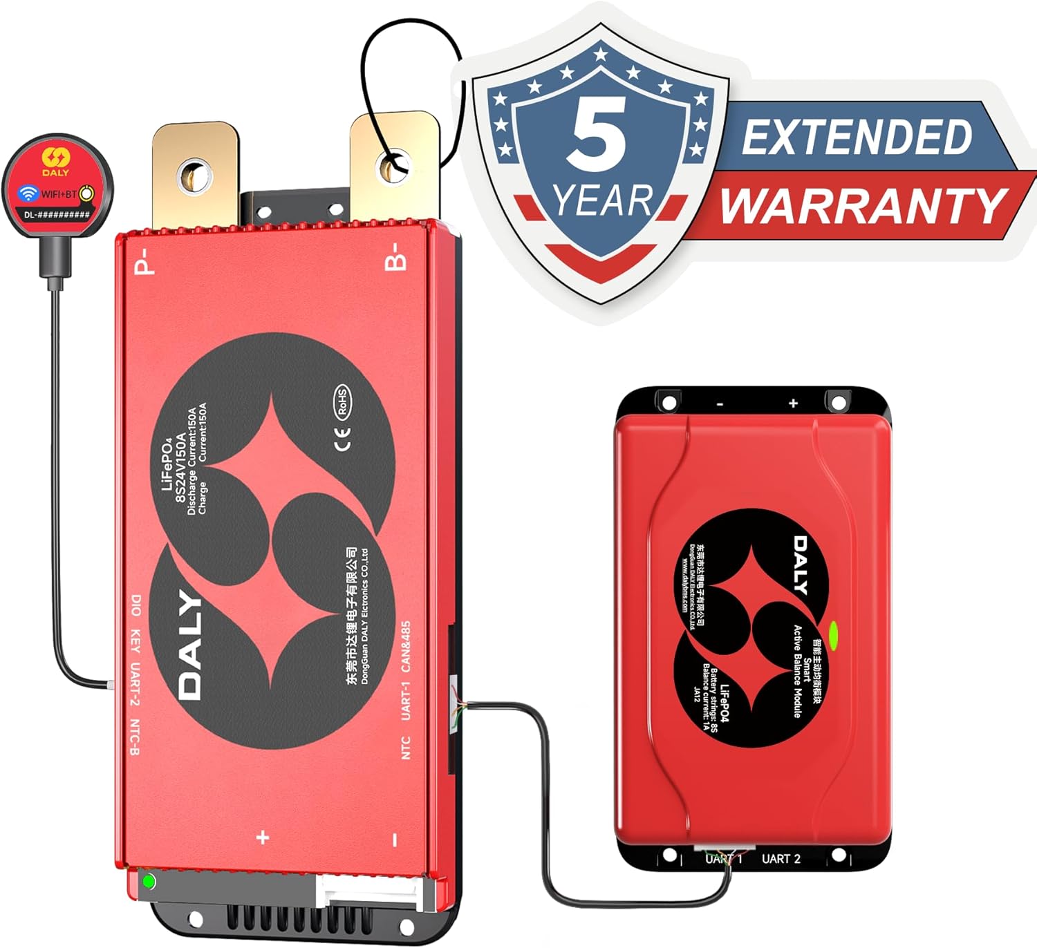
Image 9.1: DALY BMS product with an indication of a 5-year extended warranty.
10. Support
For technical assistance, warranty claims, or any questions regarding your DALY Smart BMS, please contact the seller or manufacturer directly. Refer to your purchase documentation for specific contact details.
You can also visit the official DALY BMS store on Amazon for additional product information and resources: DALY BMS Store


