
JMT X99 D4 Dual Pro
JMT X99 D4 Dual Pro Motherboard User Manual
Model: X99 D4 Dual Pro | Brand: JMT
1. Introduction
This manual provides comprehensive instructions for the installation, operation, maintenance, and troubleshooting of the JMT X99 D4 Dual Pro Motherboard. Designed for high-performance computing, this server board supports dual LGA 2011-3 V3/V4 CPUs and up to 256GB of DDR4 memory, making it suitable for demanding workloads and gaming.

Figure 1.1: JMT X99 D4 Dual Pro Motherboard overview.
2. Product Overview and Key Features
The JMT X99 D4 Dual Pro Motherboard is engineered for robust performance and expandability. Key features include:
- Dual LGA2011-3 V3/V4 CPU Support: Enables simultaneous operation of two CPUs for enhanced processing power.
- 8-Slot DDR4 Memory: Supports up to 256GB of DDR4 RAM across four channels, significantly improving memory bandwidth.
- Extensive M.2 NVMe and Wi-Fi Interface: Features 7 M.2 NVMe x4 3.0 ports, 1 M.2 NVMe x4 2.0 port, and 1 M.2 Wi-Fi slot for high-speed storage and wireless connectivity.
- Multiple PCIe Slots: Includes 3*PCIE3.0 x16 and 1*PCIE3.0 x4 for graphics cards and expansion cards.
- Dual Gigabit Ethernet: Equipped with 2*RTL811H Gigabit Ethernet ports for reliable network connectivity.
- 10 SATA 3.0 Ports: Provides ample connectivity for traditional storage devices.
- USB Connectivity: Offers 4*USB3.2 GEN1 Ports (5Gbps) and 8*USB2.0 Ports for peripheral connections.
2.1. Motherboard Layout
Understanding the motherboard layout is crucial for proper component installation. Refer to the diagram below for a detailed view of the various connectors and slots.

Figure 2.1: Detailed layout of the JMT X99 D4 Dual Pro Motherboard, highlighting key interfaces and connectors.
2.2. Memory Configuration
The motherboard supports 8 DDR4 memory slots, allowing for a maximum capacity of 256GB. For optimal performance, utilize the four-channel memory architecture.
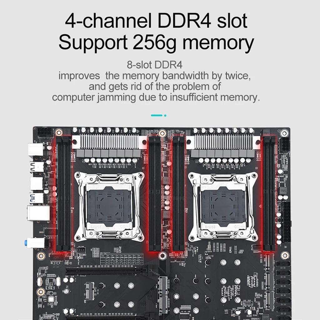
Figure 2.2: Illustration of the 8-slot DDR4 memory configuration, supporting up to 256GB.
2.3. M.2 Storage and Wi-Fi
The motherboard provides extensive M.2 support for high-speed NVMe SSDs and Wi-Fi modules, ensuring fast data transfer and flexible connectivity options.

Figure 2.3: Visual representation of the M.2 NVMe and M.2 Wi-Fi interfaces on the motherboard.
2.4. Dual CPU Support
The JMT X99 D4 Dual Pro is designed to accommodate two Intel LGA2011-3 V3/V4 CPUs, enabling powerful multi-core processing for demanding applications.

Figure 2.4: Depiction of the dual LGA2011-3 V3/V4 CPU sockets on the motherboard.
3. Setup and Installation
Before beginning installation, ensure your system is powered off and unplugged. Handle the motherboard by its edges to avoid static discharge.
3.1. Preparing the Chassis
- Install the I/O shield into the chassis's rear opening.
- Install the necessary standoffs in the chassis for the EATX form factor.
3.2. CPU Installation
- Carefully open the CPU socket retention mechanism.
- Align the CPU (LGA 2011-3 V3/V4) with the socket, ensuring the gold triangle on the CPU matches the triangle on the socket.
- Gently place the CPU into the socket without forcing it.
- Close the retention mechanism to secure the CPU. Repeat for the second CPU.
- Apply thermal paste and install compatible CPU coolers for both CPUs.
3.3. Memory (RAM) Installation
- Open the clips on both ends of the DDR4 memory slots.
- Align the notch on the DDR4 memory module with the key in the memory slot.
- Press down firmly on both ends of the memory module until the clips snap into place.
- For optimal performance, populate memory in a four-channel configuration as indicated in the motherboard manual or BIOS.
3.4. Storage Device Installation
3.4.1. M.2 NVMe SSD Installation
- Locate the desired M.2 slot (e.g., M.2 NVMe x4 3.0).
- Insert the M.2 SSD into the slot at an angle.
- Gently push down the SSD and secure it with the provided screw.
3.4.2. SATA Device Installation
- Connect one end of the SATA data cable to a SATA 3.0 port on the motherboard.
- Connect the other end of the SATA data cable to your SATA HDD/SSD.
- Connect a SATA power cable from your power supply to the storage device.
3.5. Graphics Card (GPU) Installation
- Open the retention clip on the PCIe 3.0 x16 slot.
- Align your graphics card with the slot and press down firmly until it clicks into place.
- Secure the graphics card to the chassis with screws.
- Connect any necessary PCIe power cables from your power supply to the graphics card.
3.6. Power Supply Connections
- Connect the 24-pin ATX power connector from your power supply to the 24-pin power socket on the motherboard.
- Connect the two 8-pin CPU power connectors (EPS12V) from your power supply to the corresponding sockets near the CPUs.
3.7. Front Panel and Peripheral Connections
Connect the front panel headers (power button, reset button, HDD LED, power LED, USB ports, audio jacks) to their respective pins on the motherboard. Refer to the motherboard layout diagram (Figure 2.1) for precise locations.
4. Operating Instructions
4.1. First Boot and BIOS Setup
- After all components are installed, connect your monitor, keyboard, and mouse.
- Power on your system. Press the DEL or F2 key repeatedly during startup to enter the BIOS/UEFI setup utility.
- In the BIOS, verify that all installed components (CPUs, RAM, storage) are detected correctly.
- Configure boot order to install your operating system from a USB drive or optical drive.
- Save changes and exit BIOS. The system will restart.
4.2. Operating System Installation
Follow the instructions provided by your chosen operating system (e.g., Windows, Linux) for installation. Ensure all necessary drivers for the motherboard components (chipset, network, audio, etc.) are installed after the OS is set up. These drivers are typically available on the manufacturer's website.
4.3. System Optimization
- BIOS Updates: Periodically check the JMT website for BIOS updates to improve stability, compatibility, and performance.
- Driver Updates: Keep all system drivers (chipset, GPU, network, audio) updated to their latest versions.
- Memory Configuration: Ensure memory is running in four-channel mode and at its rated speed (XMP profile if applicable) for optimal performance.
5. Maintenance
Regular maintenance helps ensure the longevity and stable operation of your motherboard and system.
- Dust Removal: Periodically clean dust from the motherboard, CPU coolers, and case fans using compressed air. Ensure the system is powered off and unplugged before cleaning.
- Cable Management: Ensure cables are neatly routed to improve airflow and prevent obstruction.
- BIOS/Firmware Updates: Check the JMT support website for the latest BIOS and firmware updates. Follow the provided instructions carefully when performing updates.
- Component Checks: Occasionally inspect all connections (power, data, expansion cards) to ensure they are secure.
6. Troubleshooting
This section addresses common issues you might encounter. For more complex problems, consult the JMT support website or a qualified technician.
6.1. No Power / No Boot
- Check Power Connections: Ensure the 24-pin ATX and both 8-pin CPU power connectors are securely plugged into the motherboard. Verify the power supply is switched on and connected to a working outlet.
- Front Panel Connections: Double-check that the power button cable from the chassis is correctly connected to the motherboard's front panel header.
- Clear CMOS: If the system fails to boot after configuration changes, try clearing the CMOS. This can usually be done by briefly shorting the CLR_CMOS pins on the motherboard or removing the CMOS battery for a few minutes.
6.2. No Display Output
- GPU Seating: Ensure the graphics card is fully seated in its PCIe slot and any necessary PCIe power cables are connected.
- Monitor Connection: Verify the display cable (HDMI, DisplayPort, DVI) is securely connected to both the graphics card and the monitor.
- Integrated Graphics: This motherboard does not have integrated graphics. A dedicated graphics card is required for display output.
6.3. Memory Issues (DRAM LED)
The JMT X99 D4 Dual Pro Motherboard features a DRAM LED indicator. If this LED remains lit, it indicates a problem with the memory. This can assist users in defining the DRAM working status easily.
- Reseat RAM: Power off the system, remove, and reinsert all RAM modules firmly.
- Test Individual Modules: If issues persist, try booting with one RAM module at a time to identify a faulty stick or slot.
- Check Compatibility: Ensure your RAM modules are compatible with the motherboard and CPU.
6.4. Storage Not Detected
- SATA/M.2 Connections: Verify that SATA data and power cables are securely connected to both the drive and the motherboard. For M.2 drives, ensure they are fully seated and secured.
- BIOS Settings: Check BIOS settings to ensure SATA controllers are enabled and M.2 slots are configured correctly (e.g., NVMe mode).
7. Specifications
Below are the detailed technical specifications for the JMT X99 D4 Dual Pro Motherboard.

Figure 7.1: Official product parameter table for the JMT X99 D4 Dual Pro Motherboard.
| Feature | Detail |
|---|---|
| Model Name | X99 D4 Dual Pro |
| Form Factor | EATX (305mm x 330mm) |
| CPU Socket | LGA 2011-3 V3/V4 Series CPU |
| RAM Slots | 8* DDR4 (Four channel) |
| Maximum RAM Capacity | 256GB |
| Graphic Socket | 3*PCIE3.0 x16, 1*PCIE3.0 x4 |
| Network | 2*Gigabit Ethernet Network Card (RTL811H) |
| SATA Ports | 10*SATA 3.0 |
| M.2 NVMe Ports | 7*M.2 2242/2260/2280 NVMe x4 3.0, 1*M.2 2242/2260/2280 NVMe x4 2.0 (NVME 8) |
| M.2 Wi-Fi | 1*M.2 Wi-Fi |
| Sound Card | ALC897 HD Audio Chip |
| PSU Connector | 2*8-pin + 1*24-pin Power supply |
| PS/2 Port | 1*PS/2 |
| USB Interface | 4*USB3.2 GEN1 Ports (5Gbps), 8*USB2.0 Ports |
| Item Weight | 3.37 pounds |
| Platform | Windows |
8. Warranty and Support
For warranty information and technical support, please refer to the official JMT website or contact your retailer. Keep your proof of purchase for warranty claims.
JMT Direct Store: Visit JMT Store on Amazon
Related documentsX99 D4 Dual Pro


Ask a question about this manual
Ask about setup, troubleshooting, compatibility, parts, safety, or missing instructions. Manuals+ will review the question and use this page’s manual context to help answer it.