1. Introduction
This manual provides comprehensive instructions for the installation, operation, and maintenance of your YUHANUS Face Recognition Access Control System. This advanced security solution offers multiple secure entry methods, including face recognition, palm vein scanning, IC card, and PIN code, making it ideal for various applications from homes to businesses. Please read this manual thoroughly before installation and operation to ensure proper functionality and safety.
2. Product Components
The YUHANUS Face Recognition Access Control System (600lbs Lock Kit) includes the following main components:

Figure 2.1: Overview of System Components
- Access Control Unit: The main unit featuring a 5-inch HD screen, dual wide-angle cameras, and multiple input methods.
- 600lb Magnetic Lock: A heavy-duty electromagnetic lock designed for secure door closure.
- Power Supply Unit: Provides stable power to the entire access control system.
- Infrared Exit Button: A touch-free sensor for exiting the secured area.
- External Doorbell: For visitor notification.
- IC Cards: For card-based access.
- Connecting Cables and Mounting Hardware: Essential for installation.

Access Control Unit

Magnetic Lock

Power Supply Unit

Infrared Exit Button

External Doorbell
3. Setup and Installation
3.1 Pre-installation Checklist
- Ensure all components listed in Section 2 are present.
- Verify the power source meets the system requirements (AC110V-240V).
- Gather necessary tools: drill, screwdriver, wire strippers, measuring tape, pencil.
- Choose appropriate mounting locations for the access control unit, magnetic lock, power supply, and exit button. Consider door type and traffic flow.
3.2 Mounting the Components
- Access Control Unit: Mount the unit at an appropriate height for face and palm recognition (typically 4-5 feet from the ground). Ensure it is securely fastened to a wall or door frame.
- Magnetic Lock: Install the magnetic lock on the door frame and the armature plate on the door itself. Ensure proper alignment for secure locking. Refer to the magnetic lock dimensions for precise placement.

Figure 3.1: Magnetic Lock Dimensions

Figure 3.2: Magnetic Lock Installation Example
- Power Supply Unit: Mount the power supply unit in a secure, dry location, preferably near a power outlet and the access control unit.

Figure 3.3: Power Supply Unit Terminals
- Infrared Exit Button: Install the exit button on the inside of the door, at a convenient height for hands-free operation.
- External Doorbell: Mount the doorbell unit outside the door, near the access control unit.
3.3 Wiring Diagram and Connections
Carefully follow the wiring diagram below to connect all components. Incorrect wiring can damage the system or pose a safety risk. If you are unsure, consult a qualified electrician.
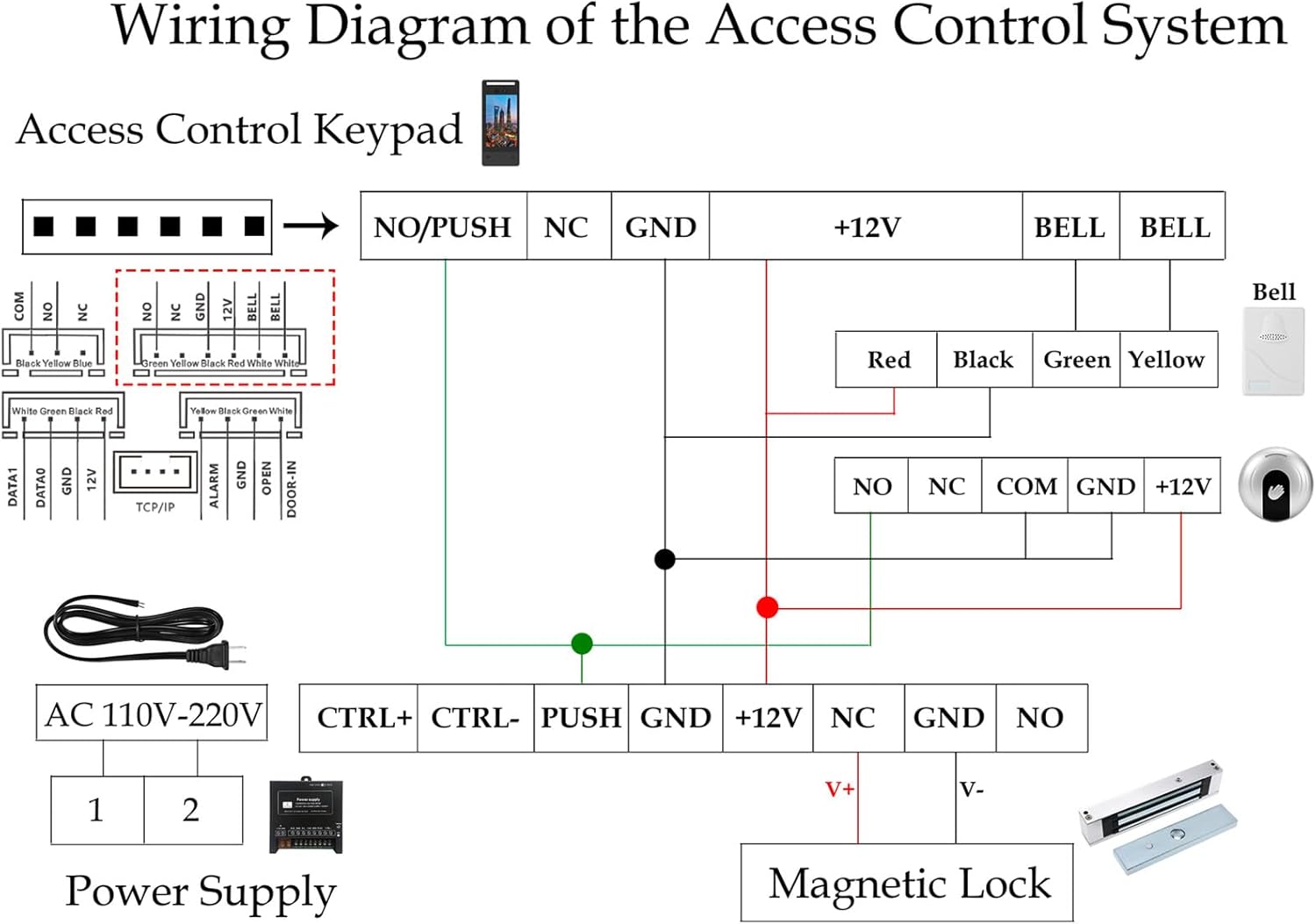
Figure 3.4: System Wiring Diagram
Key Connections:
- Connect the Access Control Unit to the Power Supply Unit (typically +12V and GND).
- Connect the Magnetic Lock to the Power Supply Unit (NO/NC and GND terminals, depending on desired lock state).
- Connect the Infrared Exit Button to the PUSH and GND terminals on the Power Supply Unit.
- Connect the External Doorbell to the BELL terminals on the Access Control Unit or Power Supply Unit as indicated.
- Ensure AC power (110V-240V) is connected to the Power Supply Unit.
Warning: Ensure power is disconnected before performing any wiring to prevent electric shock.

Figure 3.5: Typical System Layout (Outdoor/Indoor)
4. Operating Instructions
The YUHANUS Access Control System supports multiple secure entry methods. The 5-inch HD screen provides an intuitive interface for configuration and daily operation.

Figure 4.1: Supported Access Methods
4.1 User Management
Access the system menu (usually by pressing a designated button or entering an administrator PIN) to manage users. The system supports up to 5,000 users and 1 million log entries.
- Adding Users: Select "Add User" from the menu. You will be prompted to register a face, palm vein, assign an IC card, or set a PIN for the new user.
- Deleting Users: Select "Delete User" and choose the user to remove.
- Viewing Logs: Access "Log Records" to view entry and exit events.
4.2 Entry Methods
- Face Recognition: Stand directly in front of the unit, aligning your face with the on-screen guide. The system will automatically recognize and grant access if registered.
- Palm Vein Scanning: Place your palm over the designated sensor area. Ensure your palm is flat and within the scanning range.
- IC Card: Tap your registered IC card against the card reader area on the unit.
- PIN Code: Enter your assigned PIN code using the on-screen keypad and confirm.
4.3 Exiting the Secured Area
To exit, simply wave your hand in front of the Infrared Exit Button. The door will unlock momentarily.
5. Maintenance
- Cleaning: Regularly wipe the screen and camera lenses with a soft, dry, lint-free cloth. Do not use abrasive cleaners or solvents.
- Magnetic Lock: Ensure the magnetic lock and armature plate are free from debris and corrosion. Periodically check mounting screws for tightness.
- Software Updates: Check the manufacturer's website or contact support for any available firmware updates to ensure optimal performance and security.
- Power Supply: Ensure the power supply unit is well-ventilated and free from obstructions.
6. Troubleshooting
| Problem | Possible Cause | Solution |
|---|---|---|
| System not powering on. | No power to the power supply; faulty wiring; power supply issue. | Check power outlet and cable connections. Verify power supply output voltage. Recheck wiring diagram. |
| Door not unlocking. | Incorrect access method; user not registered; magnetic lock issue; wiring problem. | Ensure correct face/palm/card/PIN is used. Verify user registration. Check magnetic lock for obstructions. Inspect wiring. |
| Face/Palm recognition failure. | Poor lighting; incorrect distance/angle; dirty lens; user data corrupted. | Ensure adequate lighting. Maintain proper distance and angle. Clean camera/sensor lens. Re-register user if necessary. |
| Infrared Exit Button not working. | Sensor obstructed; wiring issue; faulty button. | Clear any obstructions. Check wiring to the power supply. Test the button for functionality. |
7. Specifications
- Model: YH-F695-P9-280
- Dimensions (Access Control Unit): Approximately 11.81 x 8.27 x 5.12 inches
- Weight: Approximately 4 pounds (total kit)
- Material: Stainless Steel (Magnetic Lock components)
- Power Input: AC110V-240V (Power Supply Unit)
- Power Output: DC12V (Power Supply Unit)
- User Capacity: Up to 5,000 users
- Log Capacity: Up to 1 million log entries
- Screen: 5-inch HD ISP Display
- Cameras: Dual Wide-Angle Cameras (1 Million Pixels)
- Lock Type: 600lb Electromagnetic Lock
- Entry Methods: Face Recognition, Palm Vein, IC Card, PIN Code
8. Warranty and Support
For warranty information and technical support, please refer to the warranty card included with your product or visit the official YUHANUS website. You may also contact the seller directly through your purchase platform for assistance.
When contacting support, please have your product model number (YH-F695-P9-280) and purchase details ready.