1. Introduction
This manual provides detailed instructions for the installation, operation, and maintenance of the IBXDTUVJ Smartgen 6110N Generator Controller. Please read this manual thoroughly before using the product to ensure proper function and safety.
The Smartgen 6110N is an advanced generator control panel designed for single generator set automation. It offers comprehensive monitoring, protection, and control functions for various generator applications.

Figure 1.1: Smartgen 6110N Generator Controller with its display showing operational data.
2. Product Overview
2.1 Key Features
- Automatic Start/Stop Control
- Generator Parameter Monitoring (Voltage, Current, Frequency, Power, RPM, Temperature, Pressure)
- Multiple Protection Functions (Over/Under Voltage, Over Current, Low Oil Pressure, High Engine Temperature)
- Configurable Inputs and Outputs
- LCD Display for clear information presentation
- USB and RS485 Communication Ports
2.2 Front Panel Components
The front panel of the Smartgen 6110N features an LCD display and various buttons for control and navigation. Understanding these components is essential for operation.

Figure 2.1: Smartgen 6110N Generator Controller with its display inactive.

Figure 2.2: Labeled components of the Smartgen 6110N front panel.
Key Labels and Functions:
- Alarm: Indicates active alarms or warnings.
- Status: Shows the current operational status of the generator.
- Up/Increase: Navigates up in menus or increases parameter values.
- Homepage/Return: Returns to the main display or previous menu.
- Set/Confirm: Enters settings menu or confirms a selection.
- Down/Decrease: Navigates down in menus or decreases parameter values.
- Auto Mode: Activates automatic operation mode.
- Start: Manually starts the generator.
- Stop Mode: Activates stop mode.
- Stop/Reset: Manually stops the generator or resets alarms.
- Manual Mode: Activates manual operation mode.
- Close/Open: Controls the generator circuit breaker (Genset).
- Load: Indicates load status.
3. Setup and Installation
3.1 Safety Precautions
Always observe the following safety guidelines during installation and operation:
- Ensure all power sources are disconnected before installation or maintenance.
- Only qualified personnel should perform electrical wiring.
- Verify correct wiring according to the provided diagrams to prevent damage to the controller or generator.
- Protect the controller from moisture, extreme temperatures, and direct sunlight.
3.2 Mounting
The controller is designed for panel mounting. Ensure adequate space for ventilation and access to wiring terminals.
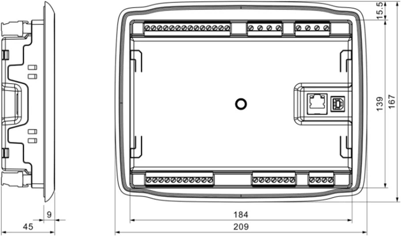
Figure 3.1: Dimensions of the Smartgen 6110N Controller (in millimeters).
Dimensions:
- Overall Dimensions: Approximately 209 mm (width) x 167 mm (height) x 45 mm (depth).
- Panel Cutout: Refer to the diagram for precise cutout dimensions, typically 184 mm x 139 mm.
3.3 Wiring Diagram
Connect the controller to the generator, battery, sensors, and actuators according to the wiring diagram below. Pay close attention to polarity and terminal designations.

Figure 3.2: Detailed wiring diagram for the Smartgen 6110N Controller.
Key Wiring Connections:
- Terminals 1-2: Emergency Stop, Battery Negative (B-), Battery Positive (B+).
- Terminals 3-6: Fuel (16A), Crank (16A), Aux Output 1 (7A), Aux Output 2 (7A).
- Terminals 7-10: Aux Output 3 (16A), Aux Output 4 (16A), Charger (D+).
- Terminals 15-22: Magnetic Pickup, Engine Temp, Oil Pressure, Fuel Level, Aux Input 1-4.
- Terminals 27-30: Gens Voltage (U, V, W, N2).
- Terminals 31-34: Mains Voltage (R, S, T, N1).
- Terminals 41-44: ECU (J1939) CAN SCR, CAN L, CAN H.
- Terminals 35-37: RS485 (Isolation) SCR, S, R.
- Terminals 23-26: Current (Rated 5A) IA, IB, IC, ICOM.
- USB Port: For PC connection and configuration.
- Ethernet Port: For network communication (if applicable).
3.4 Initial Power-Up
After completing all wiring, apply power to the controller. The display should illuminate, and the controller will perform a self-test. Follow any on-screen prompts for initial setup or calibration.
4. Operating Instructions
4.1 Basic Operation
The controller operates primarily through its front panel buttons and LCD display. Use the Up/Down buttons to navigate menus and the Set/Confirm button to select options or confirm changes.
4.2 Control Modes
- Auto Mode: The generator will automatically start and stop based on configured conditions (e.g., mains failure, scheduled run times). Press the 'Auto Mode' button to activate.
- Manual Mode: Allows for manual control of the generator. Press the 'Manual Mode' button, then use the 'Start' and 'Stop/Reset' buttons to control the generator.
- Stop Mode: The generator will remain stopped and will not start automatically. Press the 'Stop Mode' button to activate.
4.3 Display Information
The LCD display provides real-time information about the generator and controller status. This includes:
- Generator Voltage (V)
- Generator Frequency (Hz)
- Generator Current (A)
- Active Power (kW)
- Engine Speed (RPM)
- Engine Temperature (°C)
- Oil Pressure (kPa)
- Battery Voltage (V)
- Operational Status and Alarms
4.4 Parameter Settings
To access and modify controller parameters, press the 'Set/Confirm' button. Navigate through the menu using the Up/Down buttons and confirm selections with 'Set/Confirm'. Refer to the detailed programming guide (if available separately) for specific parameter definitions and ranges.
5. Maintenance
5.1 Routine Checks
- Periodically inspect the controller for any visible damage or loose connections.
- Keep the front panel and display clean using a soft, dry cloth. Avoid abrasive cleaners.
- Ensure proper ventilation around the controller to prevent overheating.
- Check wiring terminals for corrosion or looseness.
6. Troubleshooting
6.1 Common Issues and Solutions
This section provides guidance for resolving common operational problems. For complex issues, contact technical support.
| Problem | Possible Cause | Solution |
|---|---|---|
| Controller display is blank | No power supply; loose wiring. | Check battery connections and power input to the controller. Ensure wiring is secure. |
| Generator fails to start in Auto Mode | Auto Mode not selected; low fuel; low battery; engine fault. | Verify Auto Mode is active. Check fuel level, battery voltage, and engine status. Review alarm messages. |
| Alarm indicator active | Specific fault detected (e.g., low oil pressure, high temperature). | Check the display for the specific alarm message. Address the underlying issue (e.g., add oil, check cooling system). Press 'Stop/Reset' to clear the alarm after resolution. |
| Incorrect parameter readings | Sensor malfunction; incorrect calibration; loose sensor wiring. | Verify sensor connections. Check sensor functionality. Recalibrate parameters if necessary. |
7. Specifications
7.1 Technical Data
| Parameter | Value |
|---|---|
| Brand | IBXDTUVJ |
| Model | Smartgen 6110N |
| Overall Dimensions (W x H x D) | Approx. 209 mm x 167 mm x 45 mm |
| Panel Cutout Dimensions | Approx. 184 mm x 139 mm |
| Operating Voltage | DC 8V to 35V (Continuous) |
| Power Consumption | Max 3W (Standby), Max 6W (Operating) |
| Operating Temperature | -25°C to +70°C |
| Storage Temperature | -30°C to +80°C |
| Relative Humidity | 20% to 90% (non-condensing) |
| Protection Level | IP55 (front panel after installation) |
| Communication | USB, RS485 |
8. Warranty and Support
8.1 Warranty Information
Specific warranty details for the IBXDTUVJ Smartgen 6110N Generator Controller are not provided within this instruction manual. Please refer to your purchase documentation or contact the seller or manufacturer directly for warranty terms and conditions.
8.2 Technical Support
For technical assistance, troubleshooting beyond this manual, or inquiries regarding parts and service, please contact your product supplier or the manufacturer, IBXDTUVJ. Contact information is typically available on the product packaging or the seller's website.


