1. Product Overview
The eletechsup DD0612SA is a compact DC-DC step-up (boost) converter module designed to regulate and supply stable output voltages from a lower input voltage. This module is capable of converting input voltages ranging from 2.6V to 6V into selectable output voltages of 5V, 6V, 9V, or 12V, depending on the specific variant. It features high efficiency and includes multiple protection mechanisms for reliable operation.
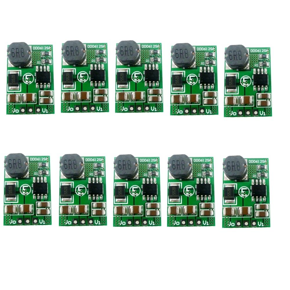
Figure 1: A set of ten eletechsup DD0612SA DC-DC boost converter modules. Each module is small, featuring a green circuit board with a prominent black inductor coil and various surface-mount components. This image shows the compact size and quantity of the product.
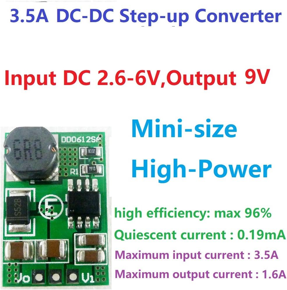
Figure 2: Detailed view of a single DD0612SA module, illustrating its key specifications such as input/output voltage ranges, maximum currents, efficiency (up to 96%), and quiescent current. The image emphasizes its compact size and high power capability.
2. Specifications
| Parameter | Description |
|---|---|
| Model Number | DD0612SA |
| Input Voltage Range | DC 2.6V to 6V (varies slightly by output voltage variant) |
| Output Voltage Options | DC 5V, 6V, 9V, 12V (±3%) |
| Maximum Output Current (5V variant) | 2.6A |
| Maximum Output Current (6V variant) | 2.5A |
| Maximum Output Current (9V variant) | 1.6A |
| Maximum Output Current (12V variant) | 1.2A |
| Working Frequency | 1 MHz |
| Efficiency | Up to 96% (typically 74%-96%) |
| Quiescent Current | 0.19 mA |
| Operating Temperature | -40°C to +85°C |
| Storage Temperature | -65°C to +150°C |
| Pin Pitch | 2.54 mm (Breadboard friendly) |
| Dimensions (L x W x H) | 23.9 x 16 x 6.2 mm |
| Weight | 2.5 g |
| Protection Features | Over Current Protection (OCP), Over Voltage Protection (OVP), Short Circuit Protection (SCP), Over Temperature Protection (OTP) |
2.1 Performance Data (9V Output Variant Example)
The following table provides reference measurement results for the 9V output variant, illustrating typical input and output current relationships at various input voltages.
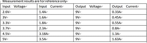
Figure 3: Reference table detailing input voltage, input current, output voltage, and output current for the 9V output variant of the DD0612SA module. This data helps in understanding the module's performance under different input conditions.
3. Setup and Connection
The DD0612SA module is designed for straightforward integration into electronic circuits. It features clearly labeled input (Vi), output (Vo), and ground (GND) pins. Ensure all connections are secure and correctly polarized before applying power.

Figure 4: Connection diagram for the DD0612SA module. The diagram clearly labels the input voltage (Vi), output voltage (Vo), and common ground (GND) pins, indicating where to connect the power source and the load.
3.1 Connection Steps:
- Identify Pins: Locate the Vi (Input Voltage), GND (Ground), and Vo (Output Voltage) pins on the module.
- Input Power Connection: Connect your DC power source's positive terminal to the Vi pin. Connect the negative terminal of your power source to the GND pin. Ensure the input voltage is within the specified range (e.g., 2.6V-6V).
- Output Load Connection: Connect the positive terminal of your load (device to be powered) to the Vo pin. Connect the negative terminal of your load to the same GND pin used for the input.
- Verify Connections: Double-check all wiring for correct polarity and secure connections to prevent damage to the module or connected devices.
4. Operating Instructions
Once properly connected, the DD0612SA module will automatically step up the input voltage to the designated output voltage. Observe the following guidelines for optimal performance:
- Input Voltage: Always ensure the input voltage remains within the module's specified operating range (e.g., 2.6V to 6V). Exceeding this range can damage the module.
- Output Load: Do not exceed the maximum output current rating for your specific module variant (e.g., 1.6A for 9V output). Operating beyond the maximum load for extended periods can lead to overheating and module failure.
- Power Consumption: The input power supplied to the module must always be greater than the desired output power, accounting for the module's efficiency and its own power consumption.
- Temperature: Operate the module within its specified operating temperature range (-40°C to +85°C) to ensure longevity and stable performance.
5. Applications
The versatility and compact size of the DD0612SA module make it suitable for a wide range of electronic projects and power solutions, including:
- Battery-powered equipment
- MCU (Microcontroller Unit) development board power supply
- Small power motors
- Cameras and video cameras
- Toy cars and boats
- Model aircraft
- Portable power banks
- LED lighting solutions
- Mobile phone chargers (DIY projects)
6. Maintenance
The DD0612SA module is designed for long-term, reliable operation with minimal maintenance. To ensure its longevity and performance, consider the following:
- Environmental Conditions: Keep the module in a dry environment, away from moisture, dust, and corrosive substances.
- Temperature Control: Avoid exposing the module to temperatures outside its specified operating and storage ranges. Adequate ventilation is recommended in enclosed applications.
- Physical Inspection: Periodically inspect the module for any signs of physical damage, loose connections, or component discoloration.
- Cleaning: If necessary, gently clean the module with a soft, dry brush or compressed air to remove dust. Do not use liquids or solvents.
7. Troubleshooting
This section addresses common issues you might encounter with the DD0612SA module.
7.1 Output Voltage is Lower Than Expected
Symptom: The measured output voltage is significantly lower than the nominal output voltage (e.g., less than 9V for a 9V variant).
Possible Cause: The input power supply is insufficient or too low.
Solution:
- Check Input Voltage: Use a multimeter to measure the input voltage directly at the Vi and GND pins of the module. Ensure it is within the specified input voltage range (e.g., 2.6V to 6V).
- Verify Input Current Capability: Confirm that your input power source can supply enough current for the module and its load. If the input current capability is too low, the input voltage may drop under load, leading to a reduced output voltage.
- Reduce Load: Temporarily reduce the load connected to the output to see if the output voltage stabilizes. If it does, your load might be drawing too much current for the input power supply or the module's maximum output current rating.
8. Important Considerations
- This is a DC-DC voltage converter module. Adhere strictly to the specified input and output parameters.
- The input voltage must not exceed the maximum input range specified for the module.
- The output power drawn by the load must not exceed the module's maximum load capacity for prolonged periods.
- The input power supplied to the module must always be greater than the output power, accounting for the module's internal power consumption and conversion losses.