1. Introduction
This manual provides detailed instructions for the installation, operation, and maintenance of the Mechanivis CWT-TM-16TC-T 16-Channel K-Type Thermocouple Temperature Acquisition Module. This module is designed for accurate temperature measurement and data acquisition in industrial environments, utilizing RS485 Modbus RTU communication.

Figure 1.1: Front view of the Mechanivis CWT-TM-16TC-T module, showing terminal blocks and model information.
2. Key Features
- Accurate Measurement: High resolution and precision for reliable temperature readings.
- High Compatibility: Supports 16 channels of K-Type thermocouples.
- Variety of Outputs: Features RS485 Modbus RTU communication for data output.
- Industrial Adaptability: Designed for robust performance in harsh industrial environments.
- Signal Conversion: Converts analog thermocouple signals to digital for easy data acquisition and transmission.
3. Specifications
The following table details the technical specifications of the CWT-TM-16TC-T module.
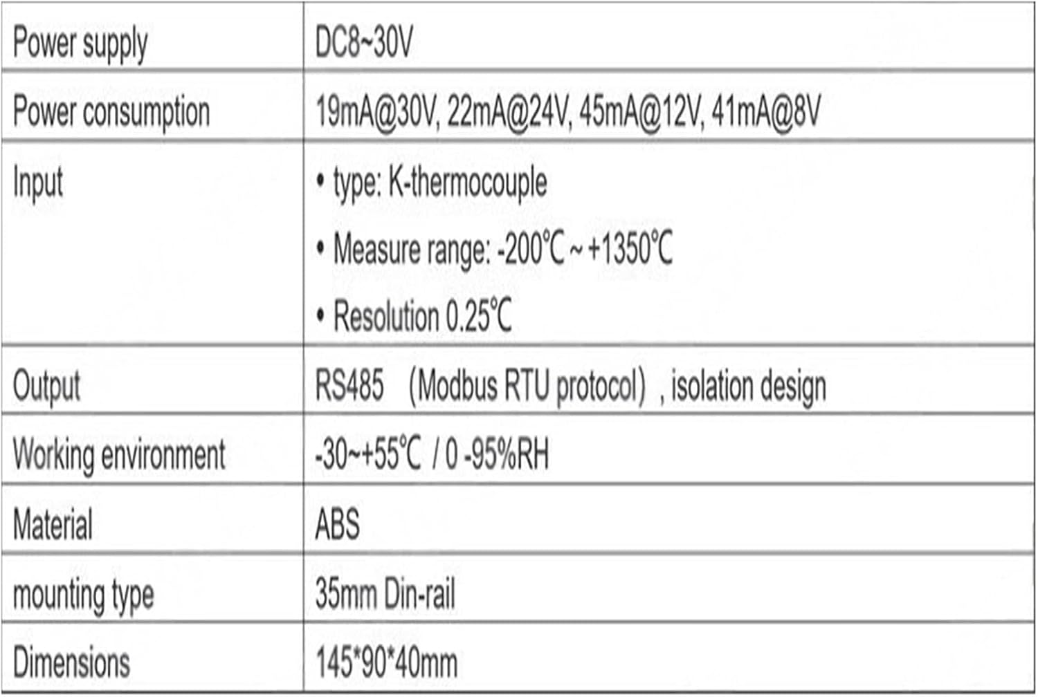
Figure 3.1: Detailed technical specifications including power supply, input type, measurement range, resolution, output, working environment, material, mounting type, and dimensions.
| Parameter | Value |
|---|---|
| Power Supply | DC 8-30V |
| Power Consumption | 19mA@30V, 22mA@24V, 45mA@12V, 41mA@8V |
| Input Type | K-Type Thermocouple |
| Measure Range | -200°C ~ +1350°C |
| Resolution | 0.25°C |
| Output | RS485 (Modbus RTU protocol), isolation design |
| Working Environment | -30 ~ +55°C / 0 - 95%RH (non-condensing) |
| Material | ABS |
| Mounting Type | 35mm DIN-rail |
| Dimensions | 145*90*40mm |
| Item Weight | 3000 Grams |
4. Setup and Installation
4.1 Physical Installation
The CWT-TM-16TC-T module is designed for 35mm DIN-rail mounting. Secure the module onto a standard DIN-rail in your control cabinet or enclosure.

Figure 4.1: Rear view of the module, illustrating the integrated clips for 35mm DIN-rail mounting.
4.2 Wiring Connections
Ensure all power is disconnected before making any wiring connections. Refer to the terminal diagram below for correct wiring.

Figure 4.2: Terminal connection diagram, detailing power, sensor, and RS485 wiring.
- Power Supply: Connect DC 8-30V to the +V (Power +) and GND (Power -) terminals.
- Thermocouple Input: Connect K-Type thermocouples to the TD(n)+ (Sensor +) and TD(n)- (Sensor -) terminals for each of the 16 channels. Ensure correct polarity.
- RS485 Communication: Connect the RS485 bus to the A (D+) and B (D-) terminals.
5. Operating Instructions
5.1 Modbus RTU Communication
The CWT-TM-16TC-T module communicates using the Modbus RTU protocol over an RS485 interface. A Modbus master device (e.g., PLC, HMI, PC with Modbus software) is required to read data from and write parameters to the module.
5.2 Reading Temperature Data
Temperature data for each of the 16 channels can be read from the specified Modbus holding registers. The data format is UINT (Unsigned Integer) with a scale factor of 0.1. This means the raw value read from the register should be divided by 10 to get the actual temperature in degrees Celsius.

Figure 5.1: Modbus register map for reading temperature values from Channel 1 to Channel 16.
| Address (hex) | Description | Format | Scale | Number of bytes | Property |
|---|---|---|---|---|---|
| 20H | Channel 1 | UINT | 0.1 | 2 | R |
| 21H | Channel 2 | UINT | 0.1 | 2 | R |
| 22H | Channel 3 | UINT | 0.1 | 2 | R |
| 23H | Channel 4 | UINT | 0.1 | 2 | R |
| 24H | Channel 5 | UINT | 0.1 | 2 | R |
| 25H | Channel 6 | UINT | 0.1 | 2 | R |
| 26H | Channel 7 | UINT | 0.1 | 2 | R |
| 27H | Channel 8 | UINT | 0.1 | 2 | R |
| 28H | Channel 9 | UINT | 0.1 | 2 | R |
| 29H | Channel 10 | UINT | 0.1 | 2 | R |
| 2AH | Channel 11 | UINT | 0.1 | 2 | R |
| 2BH | Channel 12 | UINT | 0.1 | 2 | R |
| 2CH | Channel 13 | UINT | 0.1 | 2 | R |
| 2DH | Channel 14 | UINT | 0.1 | 2 | R |
| 2EH | Channel 15 | UINT | 0.1 | 2 | R |
| 2FH | Channel 16 | UINT | 0.1 | 2 | R |
5.3 Configuring Communication Parameters
The module's communication parameters (baud rate, parity, and Modbus address) can be configured by writing to specific Modbus holding registers.

Figure 5.2: Modbus register map for configuring communication parameters and device address.
| Address (hex) | Byte order | Meaning | Description | Property |
|---|---|---|---|---|
| 10 | LO | Communication parameters | BIT<7:5> reserve BIT<4:3> 00=none 01=even 10=odd (11=odd) BIT<2:0> 000=9600 001=1200 010=2400 011=4800 100=9600 101=14400 110=19200 Initial value: 01 | RW |
| Hi | address | 1-250 Initial value: 01 | RW |
Note: The initial Modbus address is 01. The initial baud rate is 9600 bps with no parity. Refer to the table for specific bit configurations for baud rate and parity settings.
6. Maintenance
The CWT-TM-16TC-T module is designed for minimal maintenance.
- Cleaning: Periodically clean the exterior of the module with a soft, dry cloth. Do not use abrasive cleaners or solvents.
- Connections: Regularly inspect all wiring connections to ensure they are secure and free from corrosion.
- Environment: Ensure the operating environment remains within the specified temperature and humidity ranges to prevent damage.
7. Troubleshooting
- No Power Indication:
- Verify the power supply voltage is within the DC 8-30V range.
- Check power wiring for correct polarity and secure connections.
- No Communication via RS485:
- Ensure RS485 A (D+) and B (D-) connections are correct and secure.
- Verify the Modbus address of the module matches the master device's configuration.
- Check baud rate and parity settings on both the module and the master device. The initial settings are 9600 bps, no parity.
- Confirm the RS485 network is properly terminated if necessary.
- Incorrect Temperature Readings:
- Ensure K-Type thermocouples are used and connected with correct polarity to the respective channels.
- Check thermocouple integrity and ensure they are not damaged.
- Verify the scaling factor (0.1) is correctly applied when interpreting the raw Modbus data.
- Ensure the ambient temperature of the module is stable, as internal cold junction compensation relies on it.
8. Warranty and Support
For warranty information and technical support, please contact your vendor or the manufacturer, Mechanivis. Keep your purchase receipt for warranty claims.
Manufacturer: Mechanivis


