
1. Introduction
This manual provides essential information for the proper use and integration of the GODIYMODULES BPW34 and BPW34S Silicon PIN Photodiodes. These components are designed for high sensitivity and speed in detecting visible and near-infrared light. Please read this manual thoroughly before installation and operation.
2. Product Overview
The BPW34 and BPW34S are silicon PIN photodiodes featuring a compact DIP package. They offer high radiant sensitivity and a fast response time, making them suitable for various applications including optical data transmission, light barriers, and industrial control systems.
Key Features:
- Silicon PIN Photodiode technology.
- High photo sensitivity.
- Fast response time.
- Suitable for visible and near-infrared light detection.
- Compact DIP package with dimensions of 5.4 x 4.3 x 3.2 mm.
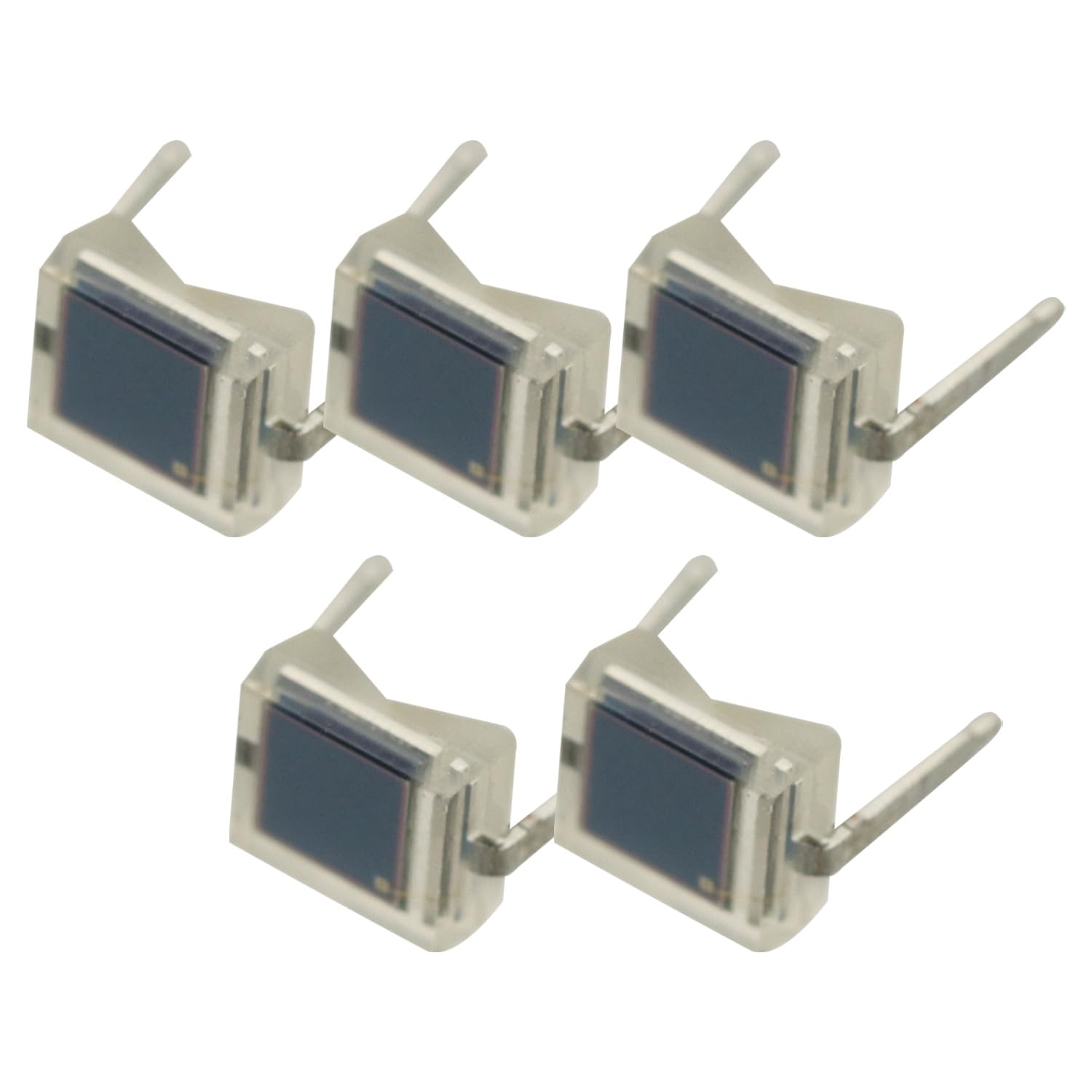
Figure 2.1: A single BPW34/BPW34S photodiode, showing its transparent housing and light-sensitive area.
3. Package Contents
Each package contains the following items:
- 5 x BPW34/BPW34S Silicon PIN Photodiodes.

Figure 3.1: Top view of five BPW34/BPW34S photodiodes included in the package.
4. Specifications
| Feature | Detail |
|---|---|
| Brand | GODIYMODULES |
| Model Name | BPW34, BPW34S |
| Included Components | 5 pcs |
| Dimensions (L x W x H) | 5.4 x 4.3 x 3.2 mm |
| Type | Silicon PIN Photodiode |
| Sensitivity | High photo sensitivity |
| Speed | High speed response |
| Light Spectrum | Visible and near-infrared |
| Compatible Devices | Cameras, Computers (PCs, laptops, tablets), Microcontrollers (Arduino, Raspberry Pi models) |
5. Setup and Connection
The BPW34/BPW34S photodiodes are typically used in either photovoltaic or photoconductive mode. Proper connection is crucial for optimal performance.
5.1 Pin Identification
The photodiode has two leads. Refer to the datasheet for specific anode and cathode identification. Typically, the longer lead is the anode and the shorter lead is the cathode, but always verify with the manufacturer's documentation or by checking the package markings.

Figure 5.1: Side view of two photodiodes, illustrating the leads for connection.
5.2 Photovoltaic Mode (Zero Bias)
In photovoltaic mode, the photodiode operates without external bias voltage. It generates a voltage proportional to the incident light. This mode is suitable for low-frequency applications where high sensitivity is required and speed is not critical.
- Connect the anode to the positive input of an amplifier (e.g., op-amp).
- Connect the cathode to the negative input or ground, depending on the circuit design.
- A transimpedance amplifier is commonly used to convert the photodiode's current into a measurable voltage.
5.3 Photoconductive Mode (Reverse Bias)
For high-speed applications, the photodiode is typically operated in photoconductive mode with a reverse bias voltage. This reduces the junction capacitance, leading to faster response times.
- Apply a reverse bias voltage across the photodiode (positive to cathode, negative to anode).
- Connect the photodiode in series with a load resistor. The current flowing through the resistor will be proportional to the incident light.
- Ensure the reverse voltage does not exceed the maximum rating (e.g., 60V as per some datasheets for similar devices).
Important: Always refer to the specific datasheet for the BPW34/BPW34S for detailed electrical characteristics and recommended operating conditions. Incorrect wiring can damage the device.
6. Operating Instructions
Once properly connected, the photodiode will convert incident light into an electrical current or voltage. The output signal can then be processed by an external circuit (e.g., an amplifier, microcontroller ADC).
6.1 Light Source Considerations
- The BPW34/BPW34S is sensitive to visible light (approx. 400-700 nm) and near-infrared light (up to approx. 1100 nm).
- For optimal performance, ensure the light source is directed towards the active area of the photodiode.
- Avoid exposing the photodiode to excessively strong light sources that could saturate the sensor or cause damage.
6.2 Signal Processing
The small current generated by the photodiode typically requires amplification. A transimpedance amplifier (TIA) is commonly used to convert the photodiode's current into a voltage, which can then be further processed or digitized.

Figure 6.1: A group of BPW34/BPW34S photodiodes, illustrating their physical form factor.
7. Maintenance
These photodiodes are solid-state devices and require minimal maintenance. However, proper handling and storage are essential for their longevity.
- Cleaning: If necessary, gently clean the transparent housing with a soft, lint-free cloth. Avoid abrasive materials or harsh chemicals.
- Storage: Store photodiodes in a dry, cool environment, away from direct sunlight and extreme temperatures. Keep them in their original packaging or an anti-static container to prevent electrostatic discharge (ESD) damage.
- Handling: Always handle the photodiodes by their leads or body, avoiding contact with the active light-sensitive area. ESD precautions should be observed when handling.
8. Troubleshooting
| Problem | Possible Cause | Solution |
|---|---|---|
| No output signal | Incorrect wiring; No light incident on the photodiode; Damaged photodiode; Faulty external circuit. | Verify pin connections (anode/cathode). Ensure light is reaching the active area. Test the photodiode with a known good circuit. Check external amplifier/measurement circuit. |
| Low sensitivity/Weak signal | Insufficient light; Photodiode operating in photovoltaic mode when photoconductive is needed; Incorrect amplifier gain. | Increase light intensity or optimize light path. Consider using photoconductive (reverse bias) mode for higher speed/sensitivity. Adjust amplifier gain. |
| Slow response time | Photodiode operating in photovoltaic mode; High load resistance in photoconductive mode. | Operate in photoconductive (reverse bias) mode. Reduce load resistance if applicable, or use a transimpedance amplifier with appropriate feedback components. |
| Erratic or noisy output | External electrical noise; Poor shielding; Grounding issues; Faulty connections. | Ensure proper shielding of the photodiode and associated circuitry. Verify all connections are secure. Implement proper grounding techniques. |
9. Warranty and Support
GODIYMODULES provides a warranty for its products as per standard terms and conditions. For specific warranty details, please refer to the purchase documentation or contact GODIYMODULES customer support.
For technical assistance, troubleshooting, or further inquiries, please visit the GODIYMODULES official website or contact their customer service department. When contacting support, please have your product model (BPW34/BPW34S) and purchase information ready.