1. Introduction
This manual provides instructions for the safe and effective use of the Preciva Crimping Tool Connector Kit. It covers product components, specifications, setup procedures, operating instructions for various connector types, maintenance guidelines, and troubleshooting tips. Please read this manual thoroughly before operating the tool.
2. Product Overview and Package Contents
The Preciva Crimping Tool Connector Kit is designed for crimping wires ranging from AWG28-16 (0.08-1.5mm²) for various electrical connectors.
2.1 Kit Components
- Ratcheting Crimping Pliers (AWG28-16 / 0.08-1.5mm²)
- 620 Pcs Connectors (2.54mm, 2.5mm JST-XH, 2.0mm JST-PH)
- 1600 Pcs Pins
- Double-layer Portable Storage Box

Figure 1: Complete Preciva Crimping Tool Connector Kit.
2.2 Connector and Pin Quantities
The kit includes a variety of connectors and pins for common applications:

Figure 2: Terminal Parameters and Quantities.
2.3 Storage Case
The kit comes with a double-layer portable storage box for organized storage and transport of all components.

Figure 3: Portable Tool Storage Suitcase.
3. Specifications
| Feature | Specification |
|---|---|
| Model Number | CP76521 |
| Crimping Range | AWG28-16 (0.08-1.5mm²) |
| Compatible Connectors | 2.0mm, 2.54mm, 3.96mm, KF2510 (Dupont, JST-XH, JST-PH, ATX, EPS, PCIE, SATA) |
| Material | Acrylonitrile Butadiene Styrene (ABS) for handle |
| Handle Type | Ergonomic, Non-slip |
| Crimping Mechanism | Ratcheting, Self-adjusting |
| Adjustable Force | Yes, via star disk adjustment |
| Item Weight | 2.27 pounds |
| Package Dimensions | 10.75 x 8.31 x 2.48 inches |
4. Setup
Before beginning any crimping task, ensure you have a clean, well-lit workspace. Identify the correct terminal and connector for your application. Select the appropriate wire gauge that matches the terminal's specifications.
4.1 Tool Features
- Upgraded Crimp Jaws: Designed for precise crimping across various wire gauges.
- Adjustable Crimping Force: A star disk allows adjustment of crimping pressure for different wire thicknesses.
- Automatic Release Device: Ensures a complete crimp cycle before releasing the handle.
- Ratcheting Mechanism: Provides consistent crimping pressure and reduces user effort.

Figure 4: Upgraded Crimp Jaws.

Figure 5: Adjustable Crimping Force Mechanism.

Figure 6: Automatic Release Device.

Figure 7: Ratchet Device.
5. Operating Instructions
Follow these general steps for crimping. Specific procedures for different connector types are detailed below.
5.1 General Crimping Steps
- Prepare the Wire: Strip the insulation from the end of the wire to the appropriate length for the terminal. Ensure the stripped wire is clean and free of frayed strands.
- Select Terminal and Die: Choose the correct terminal for your application and identify the corresponding crimping slot on the tool's jaws.
- Insert Terminal: Place the terminal into the designated crimping slot. Ensure it is seated correctly and held securely by the tool.
- Insert Wire: Insert the stripped wire into the terminal. The wire strands should be fully within the crimp barrel.
- Crimp: Squeeze the handles of the crimping tool firmly until the ratchet mechanism releases. This ensures a complete and secure crimp.
- Inspect Crimp: Remove the crimped terminal and inspect it for proper formation. The wire insulation should be crimped by the rear barrel, and the conductor by the front barrel.
5.2 Dupont 2.54mm Terminal Crimping Procedure
This procedure applies to Dupont 2.54mm terminals for AWG 32-22 (0.03-0.34mm²) wires.
- Place the terminal onto the jaw of the crimping tool.
- Begin the crimping process by squeezing the handles.
- Once crimped, insert the wire into the connector housing.
- Insert the completed connector into the circuit board or desired application.

Figure 8: Dupont Terminal Crimping Procedure.

Figure 9: Dupont Connection Examples.
5.3 JST-XH 2.5mm Crimping Procedure
This procedure applies to JST-XH 2.5mm terminals for AWG 30-20 (0.05-0.5mm²) wires.
- Place the terminal onto the jaw of the crimping tool.
- Begin the crimping process by squeezing the handles.
- Insert the crimped wire into the JST-XH connector housing.
- Combine male and female connectors.
- Insert the completed connector into the circuit board or desired application.

Figure 10: JST-XH 2.5mm Crimping Procedure.
5.4 JST-PH 2.0mm Crimping Procedure
This procedure applies to JST-PH 2.0mm terminals for AWG 32-22 (0.03-0.34mm²) wires.
- Place the terminal onto the jaw of the crimping tool.
- Begin the crimping process by squeezing the handles.
- Insert the crimped wire into the JST-PH connector housing.
- Combine male and female connectors.
- Insert the completed connector into the circuit board or desired application.

Figure 11: JST-PH 2.0mm Crimping Procedure.
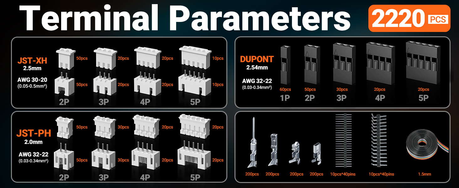
Figure 12: JST-XH and JST-PH Connection Examples.
5.5 Applications
The crimping tool and connectors are suitable for a wide range of applications, including computer and server maintenance, automotive electronics, and various industrial settings.

Figure 13: Wide Range of Applications.
6. Maintenance
Proper maintenance ensures the longevity and performance of your crimping tool.
- Cleaning: After each use, wipe down the crimping tool with a clean, dry cloth to remove any debris or residue.
- Lubrication: Periodically apply a light machine oil to the pivot points and moving parts of the tool to ensure smooth operation.
- Storage: Store the crimping tool and connectors in the provided storage box in a dry, clean environment to prevent rust and damage.
- Inspection: Regularly inspect the crimping jaws for wear or damage. Do not use the tool if the jaws are visibly damaged.
7. Troubleshooting
This section addresses common issues that may arise during the use of the crimping tool.
| Problem | Possible Cause | Solution |
|---|---|---|
| Poor crimp quality (loose or deformed) | Incorrect die size for terminal/wire; Insufficient crimping force; Improper wire stripping. | Ensure correct die selection. Adjust crimping force using the star disk. Verify wire is stripped to the correct length and fully inserted. |
| Tool handles stuck or difficult to operate | Lack of lubrication; Debris in mechanism; Over-crimping. | Clean and lubricate pivot points. Check for and remove any obstructions. Ensure the ratchet mechanism completes its cycle. |
| Terminal not holding in connector housing | Terminal not fully crimped; Incorrect terminal type for housing. | Ensure the terminal is fully crimped and the locking tabs are engaged. Verify the terminal matches the connector housing. |
8. Customer Support
For assistance with product use or any concerns, please contact Preciva customer support. Our dedicated team is available to provide prompt solutions and ensure your satisfaction.
Refer to the product packaging or the official Preciva website for current contact information.