1. Introduction
This manual provides comprehensive instructions for the installation, configuration, and operation of your SODOLA 8 Port 10G L3 Managed SFP+ Network Switch. This device is designed to deliver high-speed network connectivity and advanced management capabilities for demanding network environments. Please read this manual thoroughly before using the product to ensure proper setup and optimal performance.
2. Package Contents
Verify that all items listed below are present in your product package. If any item is missing or damaged, please contact your vendor.
- SODOLA 8 Port 10G Managed Ethernet Switch (Model: SL-SWTGW3C8F)
- Power Adapter x 1
- Console Cable x 1
- Footrests x 4
- Product Manual x 1
Note: SFP+ transceivers are NOT included and must be purchased separately.
3. Product Overview
3.1 Front Panel
The front panel of the SODOLA 8 Port 10G L3 Managed SFP+ Network Switch features eight SFP+ ports, a console port, and LED indicators for system status and power.

Image 3.1: Front view of the SODOLA 8 Port 10G L3 Managed SFP+ Network Switch, showing the eight SFP+ ports, console port, and status LEDs.
- SFP+ Ports (1-8): Eight 10Gb SFP+ ports for high-speed fiber or DAC connections. These ports support 1G, 2.5G, and 10G SFP+ modules.
- Console Port: RJ45 port for command-line interface (CLI) access.
- SYS LED: System status indicator.
- PWR LED: Power indicator.
- Reset Button: Press and hold for 8 seconds to restore factory settings.
3.2 Rear Panel
The rear panel includes mounting holes, ground screws, and the DC power input.

Image 3.2: Rear view of the SODOLA 8 Port 10G L3 Managed SFP+ Network Switch, highlighting wall mounting holes, DC power input, and ground screws.
- Wall Mounting Holes: For secure wall installation.
- DC 12V 2A Input: Power connection for the switch.
- Ground Screws: For grounding the device to prevent electrical interference.
4. Setup
4.1 Hardware Installation
The switch supports both desktop placement and wall mounting.
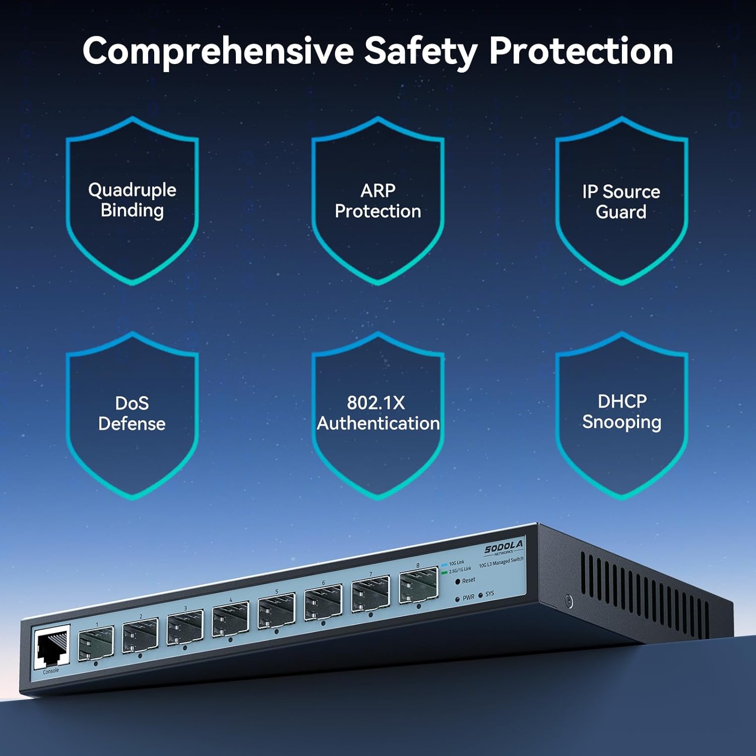
Image 4.1: Illustration of the SODOLA switch in both desktop and wall-mounted configurations.
- Desktop Placement: Attach the provided footrests to the bottom of the switch and place it on a stable, flat surface. Ensure adequate ventilation around the device.
- Wall Mounting: Use appropriate screws (not included) to secure the switch to a wall using the wall mounting holes on the rear panel. Ensure the mounting surface is strong enough to support the switch's weight.
- Power Connection: Connect the power adapter to the DC 12V 2A input on the rear panel and plug it into a power outlet. The PWR LED on the front panel should illuminate.
- Grounding: For optimal safety and to prevent electrical interference, connect a grounding wire (not included) to the ground screws on the rear panel and to a suitable ground source.
4.2 Initial Configuration (Web Management Interface)
The switch is managed via a web-based interface. Follow these steps for initial access:

Image 4.2: Steps for accessing the web management interface, including adjusting PC network settings and logging in.
- Connect PC: Connect your computer directly to one of the SFP+ ports using a compatible SFP+ module and cable. Ensure your PC's network adapter is configured to operate at 10G or 2.5G.
- Adjust PC Network Settings: Temporarily configure your PC's IP address to be in the same subnet as the switch's default IP. The default IP address for the switch is 192.168.2.1. For example, set your PC's IP to 192.168.2.10 with a subnet mask of 255.255.255.0.
- Access Web Interface: Open a web browser and navigate to
http://192.168.2.1. - Login: Enter the default credentials:
- User Name: admin
- Password: admin
- Change Default Credentials: For security purposes, it is highly recommended to change the default username and password immediately after the first login.
5. Operation
5.1 Layer 3 Management Features
This L3 Managed switch offers a robust set of features for advanced network control and optimization:
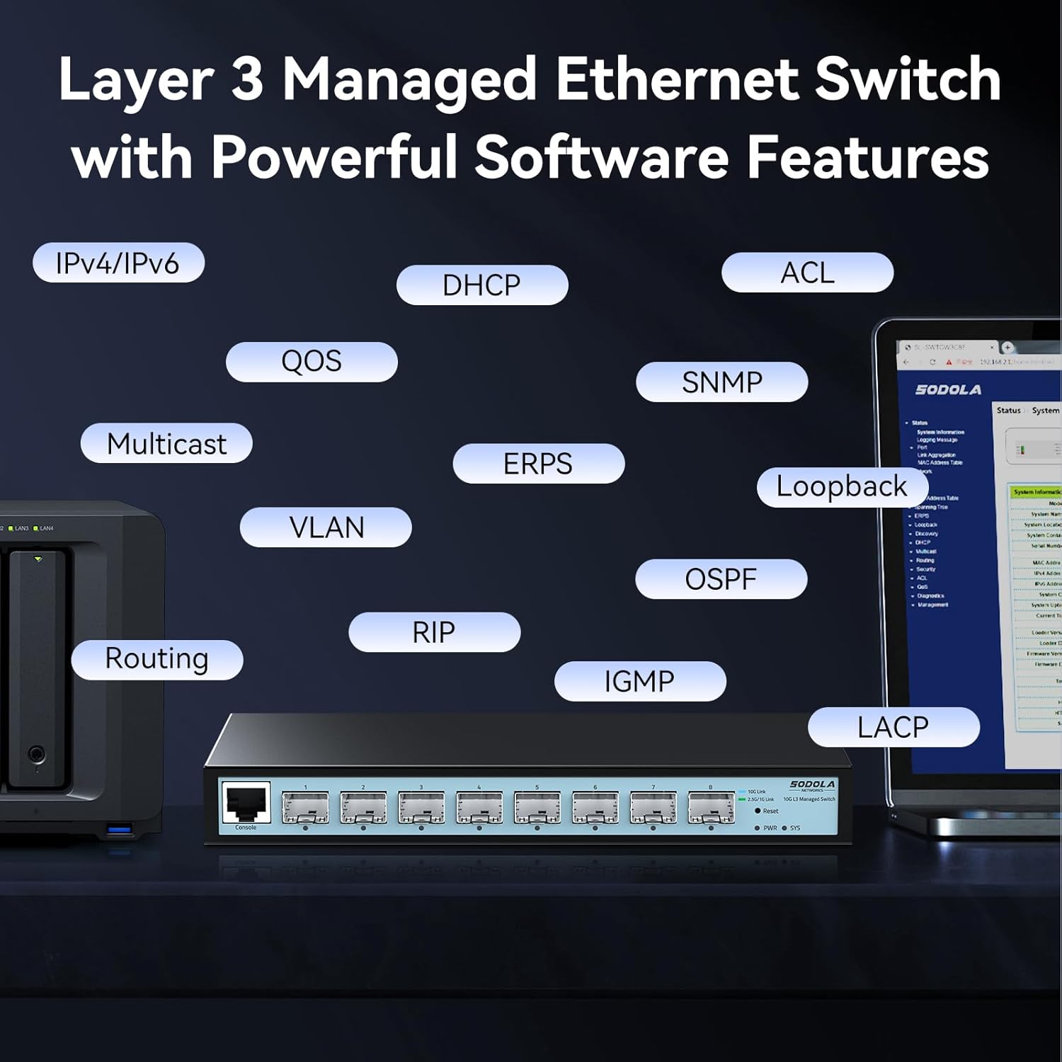
Image 5.1: Visual representation of the Layer 3 management capabilities, including IPv4/IPv6 Routing, DHCP, LACP, VLAN, QoS, IGMP, STP, SNMP, ACL, Multicast, ERPS, Loopback, and OSPF.
- IPv4/IPv6 Routing: Enables routing between different IP subnets.
- DHCP: Dynamic Host Configuration Protocol for automatic IP address assignment.
- LACP (Link Aggregation Control Protocol): Combines multiple physical links into a single logical link for increased bandwidth and redundancy.
- VLAN (Virtual Local Area Network): Segments the network into logical broadcast domains for improved security and performance.
- QoS (Quality of Service): Prioritizes network traffic to ensure critical applications receive sufficient bandwidth.
- IGMP (Internet Group Management Protocol): Manages multicast group memberships.
- STP (Spanning Tree Protocol): Prevents network loops.
- SNMP (Simple Network Management Protocol): Allows network administrators to monitor and manage network devices.
- ACL (Access Control List): Filters network traffic based on defined rules.
- DoS Defense: Protects against Denial of Service attacks.
- OSPF (Open Shortest Path First): A routing protocol for large enterprise networks.
Detailed configuration guides for each feature are available within the web management interface.
5.2 Port Speed Configuration
The SFP+ ports on this switch are adaptive, supporting 1G, 2.5G, and 10G speeds. By default, ports auto-negotiate 10G/2.5G. To connect 1G devices, manual configuration is required.

Image 5.2: Web interface showing port settings for manual speed configuration (10G/2.5G or 10G/1000M).
- Login: Access the web management interface.
- Navigate to Port Settings: Locate the "Port Setting" section in the management interface.
- Select Port: Choose the specific SFP+ port you wish to configure.
- Set Speed: Manually set the port speed to 10G/1G for 1G devices, or 10G/2.5G for 2.5G devices, ensuring compatibility with your SFP+ module and connected device.
- Apply Settings: Click "Apply" to save the changes.
- Save Configuration: After making any changes, navigate to the "Tools" or "System" section and select "Save" to permanently store the configuration. Changes are not saved across power cycles until explicitly saved.

Image 5.3: Reminder to save configuration changes within the web interface to ensure they persist after a power cycle.
6. Maintenance
6.1 Fanless Design
The SODOLA switch features a fanless design, ensuring silent operation and reducing power consumption. This design relies on natural heat dissipation through its metal casing. Ensure the switch is placed in a location with adequate airflow to prevent overheating.
6.2 Safety and Protection
The switch incorporates several safety and protection features to ensure stable and reliable operation:

Image 6.1: Overview of the switch's comprehensive safety features, including Quadruple Binding, ARP Protection, IP Source Guard, DoS Defense, 802.1X Authentication, and DHCP Snooping.
- 6KV Lightning Protection: Provides protection against electrical surges, enhancing stability during adverse weather conditions.
- Quadruple Binding: Enhances network security by binding IP, MAC, VLAN, and Port information.
- ARP Protection: Defends against ARP spoofing attacks.
- IP Source Guard: Prevents unauthorized IP addresses from accessing the network.
- DoS Defense: Mitigates various Denial of Service attacks.
- 802.1X Authentication: Provides port-based network access control.
- DHCP Snooping: Filters untrusted DHCP messages.
7. Troubleshooting
- Cannot access web management interface:
- Ensure your PC's IP address is in the same subnet as the switch (default 192.168.2.1).
- Verify that all devices in the connection chain (switch port -> module -> cable -> PC/NIC) are operating at the SAME speed (e.g., all 10G or all 2.5G). Mixed speeds can block access.
- Clear your browser cache.
- Try using a different web browser.
- Ensure the switch is powered on and the SYS LED is stable.
- 1G device not connecting or slow:
- The default port rate is 10G/2.5G adaptive. To connect 1G devices, you must manually set the port speed to 10G/1G via the management interface.
- Ensure you are using 1G-compatible SFP+ modules and cables for 1G connections.
- Configuration changes are lost after reboot:
- Always remember to explicitly save your configuration changes through the web management interface (e.g., "Tools" -> "Save") after making adjustments. Changes are not automatically saved to persistent memory.
- Network loops or instability:
- Ensure Spanning Tree Protocol (STP) or Rapid Spanning Tree Protocol (RSTP) is enabled on the switch to prevent network loops, especially in complex topologies.
- Management interface crashes when sending large ICMP packets:
- Avoid sending excessively large ICMP packets (e.g., 9K MTU ICMPs) directly to the switch's management interface, as this may cause it to become unresponsive, requiring a power cycle.
- SFP+ modules not detected:
- Ensure the SFP+ modules are fully inserted and compatible with the switch.
- Verify that the modules are functioning correctly.
8. Specifications

Image 8.1: Detailed specifications and dimensions of the SODOLA 8 Port 10G L3 Managed SFP+ Network Switch.
| Feature | Description |
|---|---|
| Model | SL-SWTGW3C8F (8X10G SFP+(L3 Managed)) |
| Interface Type | 8 * 10G SFP+ Ports (Transceivers NOT Included) |
| Switching Capacity | 160Gbps |
| Packet Forwarding Rate | 119.04Mpps |
| Packet Buffer | 12Mbit |
| MAC Address Table | 16K |
| Jumbo Frame | 10K |
| Surge Protection | 6KV |
| Power Supply | 12V 2A |
| No-load Power | 3.7W |
| Operating Temperature | 0~40°C |
| Product Dimensions | 222 x 126 x 28 mm (8.66 x 4.96 x 1.1 inches) |
| Item Weight | 0.91 Kilograms (2.01 pounds) |
| Case Material | Metal |
| Compatible Devices | Desktop, Laptop, Router |
9. Warranty and Support
SODOLA products are designed for reliability and performance. For specific warranty information, please refer to the warranty card included with your product or contact your point of purchase. While direct manufacturer support contact information is not always publicly available, for technical assistance or troubleshooting, please refer to the comprehensive documentation within the web management interface or consult the vendor from whom the product was purchased.
Regularly check the manufacturer's website (if available) for firmware updates and additional resources.


