
1. Introduction
This manual provides detailed instructions for the installation, operation, and maintenance of your Plyisty H81 LGA 1150 Micro ATX Motherboard. Please read this guide thoroughly before proceeding with installation to ensure proper setup and to maximize the performance and longevity of your system. Keep this manual for future reference.
2. Product Overview
The Plyisty H81 motherboard is designed for Intel LGA 1150 processors, offering a stable and efficient platform for your PC build. It features an H81 chipset, DDR3 memory support, and modern connectivity options including M.2 NVMe/NGFF and SATA 3.0.
Key Features:
- CPU Support: LGA 1150 socket for Intel 4th generation Core i3/i5/i7, Xeon E3 V3, Celeron G, and G-series 22NM CPUs.
- Memory: Two 240-pin DDR3 SDRAM slots, supporting up to 16GB at 1066/1333/1600 MHz in dual-channel architecture.
- Storage: High-speed M.2 interface (NVMe/NGFF compatible) and three SATA 3.0 (6GB/s) ports.
- Graphics Output: Integrated VGA and HDMI multimedia interfaces for 1080p video output (requires CPU with integrated graphics).
- Robust Design: 8-layer PCB construction, 6-phase power design, and all solid capacitors for enhanced stability and durability.
- Power: 24+4 pin power connector.
Motherboard Layout:
Below are images illustrating the various components and ports of the motherboard.
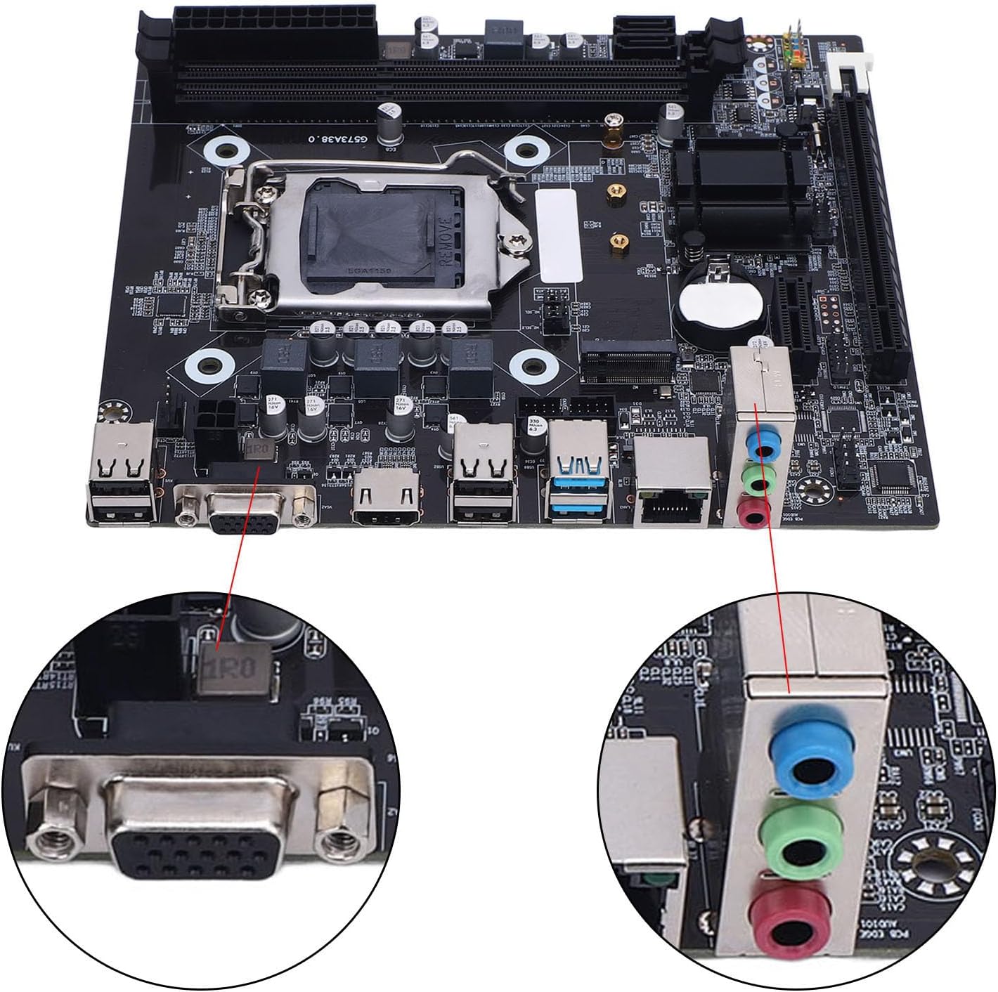
Figure 2.1: Overall view of the Plyisty H81 LGA 1150 Micro ATX Motherboard, showcasing its various components and slots.

Figure 2.2: Stable Performance Architecture highlighting LGA1150 Socket, 6-Phase Power Design, and Dual Channel DDR3 Memory support.

Figure 2.3: Flexible Expansion & Upgrade Options, detailing PCIe x16 for GPU, M.2 NVMe+NGFF Support, and SATA 3.0 High-Speed Storage.

Figure 2.4: Complete Connectivity, illustrating the rear I/O panel with VGA, HDMI, USB 2.0/3.0, RJ45 LAN, and Audio ports.
3. Setup & Installation
Follow these steps carefully to install your motherboard and its components.
3.1. CPU Installation
Ensure the CPU socket lever is open before placing the CPU. Handle the CPU by its edges to avoid touching the pins or contacts.

Figure 3.1: CPU Installation Steps. Follow the numbered sequence for correct CPU placement.
- Press down on the lever and lift it: Gently push the CPU socket lever down and then outward to release it from its locked position, then lift it up.
- Open CPU cover: Carefully open the metal CPU retention frame.
- Align the triangle symbols: Match the small golden triangle on the CPU with the corresponding triangle on the CPU socket. Gently place the CPU into the socket without forcing it.
- Remove CPU plastic cover: The plastic cover will detach automatically or can be removed once the CPU is seated.
- Align the groove and lower the lever: Ensure the CPU is perfectly seated. Close the metal retention frame, align the lever with its groove, and press it down until it locks into place.
Important Considerations:
- Do not touch CPU contacts with your hands.
- Do not touch CPU pins on the motherboard.
3.2. Memory (RAM) Installation
Locate the two DDR3 DIMM slots. Open the clips on both ends of the slot. Align the memory module with the slot, ensuring the notch on the module matches the key in the slot. Press down firmly on both ends of the memory module until the clips snap into place.
3.3. M.2 NVMe/NGFF Storage Installation
Identify the M.2 slot on the motherboard. Insert the M.2 drive at an angle into the slot. Push it down and secure it with the provided screw. Ensure the jumper settings are correct for NVMe or NGFF mode if applicable.
3.4. SATA Storage Installation
Connect your SATA hard drives or SSDs to the SATA 3.0 ports using SATA data cables. Connect the other end of the data cable to your storage device. Ensure your power supply has SATA power connectors for these devices.
3.5. Power Supply Connection
Connect the 24-pin ATX power connector from your power supply to the main power socket on the motherboard. Also, connect the 4-pin CPU power connector to the corresponding socket near the CPU.
3.6. I/O Device Connections
Connect your monitor to either the VGA or HDMI port on the rear I/O panel. Connect USB devices, Ethernet cable, and audio peripherals to their respective ports.
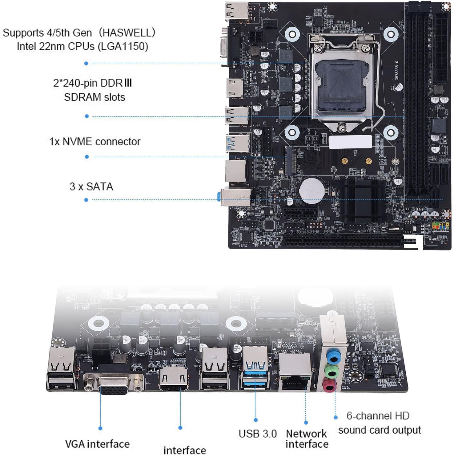
Figure 3.2: Rear I/O Panel. Connect your peripherals to these ports.
4. Operating Instructions
4.1. Initial Power On
After all components are securely installed and connected, ensure your power supply is switched on. Press the power button on your PC case. The system should power on and display the BIOS/UEFI splash screen.
4.2. BIOS/UEFI Access
To enter the BIOS/UEFI setup utility, press the DEL or F2 key repeatedly during the initial boot sequence. From here, you can configure boot order, system time, and other advanced settings.
4.3. Operating System Installation
Insert your operating system installation media (USB drive or DVD) and set it as the primary boot device in the BIOS/UEFI. Follow the on-screen instructions to install your preferred operating system.
5. Specifications
| Feature | Specification |
|---|---|
| Brand | Plyisty |
| Model Name | Plyisty295cn7soif |
| CPU Socket | LGA 1150 |
| Chipset | Intel H81 |
| Compatible Processors | Intel Core i3-4xxx, i5-4xxx, i7-4xxx, Xeon E3-12xx V3, Celeron G1xxx, G-series 22NM |
| RAM Memory Technology | DDR3 |
| Memory Slots | 2 x 240-pin DDR3 DIMM |
| Max Memory Size | 16 GB |
| Memory Clock Speed | 1066/1333/1600 MHz |
| Storage Interface | 1 x M.2 (NVMe/NGFF), 3 x SATA 3.0 (6GB/s) |
| Graphics Interface | Integrated (VGA, HDMI) |
| PCIe Slots | 1 x PCIe x16, 1 x PCIe x1 |
| USB Ports | 6 total (mix of USB 2.0 and USB 3.0) |
| Ethernet Ports | 1 |
| Audio Output | 6-channel HD sound |
| Main Power Connector | 24-pin |
| Form Factor | Micro ATX |
6. Troubleshooting
If you encounter issues, refer to the following common troubleshooting steps:
6.1. No Power
- Ensure the power supply unit (PSU) is switched on and connected to a working power outlet.
- Verify that the 24-pin and 4-pin power connectors are securely plugged into the motherboard.
- Check the front panel power button connection to the motherboard.
6.2. No Display
- Confirm that your monitor is connected to the correct video output port (VGA or HDMI) on the motherboard.
- Ensure your CPU has integrated graphics if you are not using a dedicated graphics card.
- Reseat the RAM modules. Incorrectly seated RAM is a common cause of no display.
- If using a dedicated graphics card, ensure it is properly seated in the PCIe slot and has adequate power.
6.3. System Instability or Random Restarts
- Check all power connections, especially to the CPU and motherboard.
- Ensure CPU cooler is properly installed and making good contact with the CPU. Overheating can cause instability.
- Test memory modules individually if you have multiple.
- Update BIOS/UEFI to the latest version from the manufacturer's website if available.
7. Warranty & Support
7.1. Warranty Information
This Plyisty H81 Motherboard comes with a manufacturer's warranty of 90 days from the date of purchase. Please retain your proof of purchase for warranty claims.
7.2. Technical Support
For technical assistance, troubleshooting beyond this manual, or warranty inquiries, please contact your retailer or the Plyisty customer support. Refer to the product packaging or the seller's website for contact details.