1. Introduction
This manual provides essential information for the safe and effective operation of your HY HUANYANG Variable Frequency Drive (VFD) Model GT-2R2G-2. This VFD is designed to convert single-phase 200-230V AC power into three-phase 200-230V AC power, enabling the use of three-phase motors up to 3 horsepower (2.2kW) from a single-phase supply. Please read this manual thoroughly before installation, operation, or maintenance.

Figure 1: Front view of the HY HUANYANG Variable Frequency Drive, showing the control panel and ventilation.
2. Safety Information
WARNING: Electrical shock hazard. Only qualified personnel should perform installation and maintenance.
- Always disconnect power before performing any wiring or maintenance.
- Ensure proper grounding of the VFD and the motor.
- Do not connect the VFD output to anything other than a three-phase motor. It cannot be used as a general three-phase power source.
- Verify that the VFD's voltage and power rating match your motor's requirements. The VFD must have a greater or equal power rating than the motor.
- High voltage exists inside the VFD even after power is disconnected. Wait at least 5 minutes after power-off for capacitors to discharge before touching internal components.
- Install the VFD in a clean, dry, and well-ventilated environment, away from direct sunlight, corrosive gases, and flammable materials.

Figure 2: A notice highlighting key considerations for VFD usage, including power compatibility and limitations.
3. Setup and Installation
3.1 Physical Installation
Mount the VFD securely in a suitable enclosure or location, ensuring adequate clearance for ventilation. Refer to the dimensions below for planning.

Figure 3: Diagram illustrating the physical dimensions of the VFD unit, including height, width, and depth in inches and centimeters.
3.2 Wiring Instructions
Carefully follow the wiring diagrams. Incorrect wiring can damage the VFD, motor, or cause injury.
- Input Power Connection: For single-phase 220V AC input, connect the live and neutral wires to the R and S terminals of the VFD. Note: Some older documentation may incorrectly suggest connecting to R and T. Always use R and S for single-phase input.
- Output Power Connection: Connect the three-phase motor to the U, V, W terminals of the VFD. Ensure correct phase sequence for desired motor rotation.
- Grounding: Connect the ground wire from both the power supply and the motor to the VFD's ground terminal (marked with ⊕ or PE).
- Braking Resistor (Optional): If dynamic braking is required, connect an appropriate braking resistor to the VFD's P+ and N- terminals.
- Control Circuit Terminals: For external control (e.g., remote start/stop, speed control potentiometer, RS-485 communication), refer to the detailed control circuit diagram.

Figure 4: Illustrative wiring diagram showing how to connect single-phase 220V input (R, S terminals) to the VFD, and the VFD's three-phase output (U, V, W terminals) to an asynchronous motor. An optional braking resistor connection is also depicted.

Figure 5: Close-up of the VFD's control circuit terminals, indicating connections for 485+, 485-, +10V, GND, S1-S7, AI1, AI2, AO1, AO2, COM, PW, +24V, HDI, HDO, RO1A, RO1B, RO1C.
3.3 Initial Parameter Settings
The VFD factory default frequency is typically 50Hz. If your motor's rated frequency is also 50Hz, the drive can often be used directly. For 60Hz motors or specific application requirements, parameter adjustments will be necessary. Refer to the full programming manual for detailed parameter settings.
4. Operating Instructions
The VFD features an intuitive control panel for direct operation and parameter adjustment.

Figure 6: Detailed view of the VFD's control panel with labels for various keys and the digital display.
4.1 Control Panel Functions
- Digital Display: Shows current frequency, output voltage, current, and error codes.
- PRG/ESC (Program/Escape) Key: Enters/exits parameter programming mode.
- DATA SET Key: Confirms parameter changes or enters sub-menus.
- SHIFT Key: Moves cursor during parameter editing.
- RUN Key: Starts the motor.
- ▲ / ▼ (Up/Down) Keys: Adjust frequency, navigate parameters, or change values.
- QUICK JOG Key: Initiates a quick, temporary run at a preset jog frequency.
- STOP/RST (Stop/Reset) Key: Stops the motor or resets fault conditions.
- Speed Controller (Optional): A rotary potentiometer for manual frequency adjustment.
4.2 Basic Operation Sequence
- Ensure all wiring is correct and secure.
- Apply input power to the VFD.
- Set desired frequency using the control panel keys or external potentiometer.
- Press the RUN key to start the motor.
- To stop the motor, press the STOP/RST key.
4.3 Advanced Functions
The VFD supports various advanced functions including RS-485 communication, remote potentiometer speed control, and remote switch start/stop. Refer to the comprehensive programming manual for detailed setup of these features.

Figure 7: Image showing the integrated cooling fan on the VFD unit, essential for maintaining optimal operating temperature.
5. Maintenance
Regular maintenance ensures optimal performance and extends the lifespan of your VFD.
- Cleaning: Periodically clean the VFD's exterior and ventilation openings to prevent dust accumulation, which can hinder cooling. Use a soft, dry cloth. Do not use liquid cleaners.
- Inspection: Regularly inspect wiring connections for tightness and signs of wear or damage. Check for any unusual noises or odors during operation.
- Environment: Ensure the operating environment remains within specified temperature and humidity ranges.
6. Troubleshooting
This section addresses common issues. For complex problems or error codes not listed, contact technical support.
Common Issues and Solutions:
- VFD does not power on:
Check input power supply and connections. Ensure the circuit breaker is on. - Motor does not start:
Verify wiring to the motor (U, V, W terminals). Check if the RUN command is active. Ensure no fault codes are displayed. Confirm motor parameters are correctly set in the VFD. - Motor runs in the wrong direction:
Reverse any two of the three output wires (U, V, W) connected to the motor. - Overcurrent/Overload fault:
Check motor load. Ensure motor and VFD power ratings are compatible. Verify acceleration/deceleration times are not too short. - Overvoltage/Undervoltage fault:
Check input power supply voltage. Ensure deceleration time is not too short, especially with high inertia loads. - Braking Resistor Issues:
If experiencing issues with braking, ensure the braking resistor is correctly sized and wired to the P+ and N- terminals. Incorrect resistor values or wiring can lead to malfunction or damage.
If an error code appears on the digital display and you are unsure how to proceed, please contact HY HUANYANG customer service for assistance.
7. Specifications
| Feature | Specification |
|---|---|
| Model Name | GT-2R2G-2 |
| Input Voltage | 200-230V AC (Single-Phase or Three-Phase) |
| Output Voltage | 200-230V AC (Three-Phase) |
| Rated Motor Power | ≤3HP (2.2 KW) |
| Rated Output Current | 10 Amps |
| Product Dimensions | 6.7 x 5.1 x 6.3 inches |
| Item Weight | 4.89 pounds |
| Control Method | DPS Vector Control |
| Communication | RS-485 support |
| Certifications | CE listed |
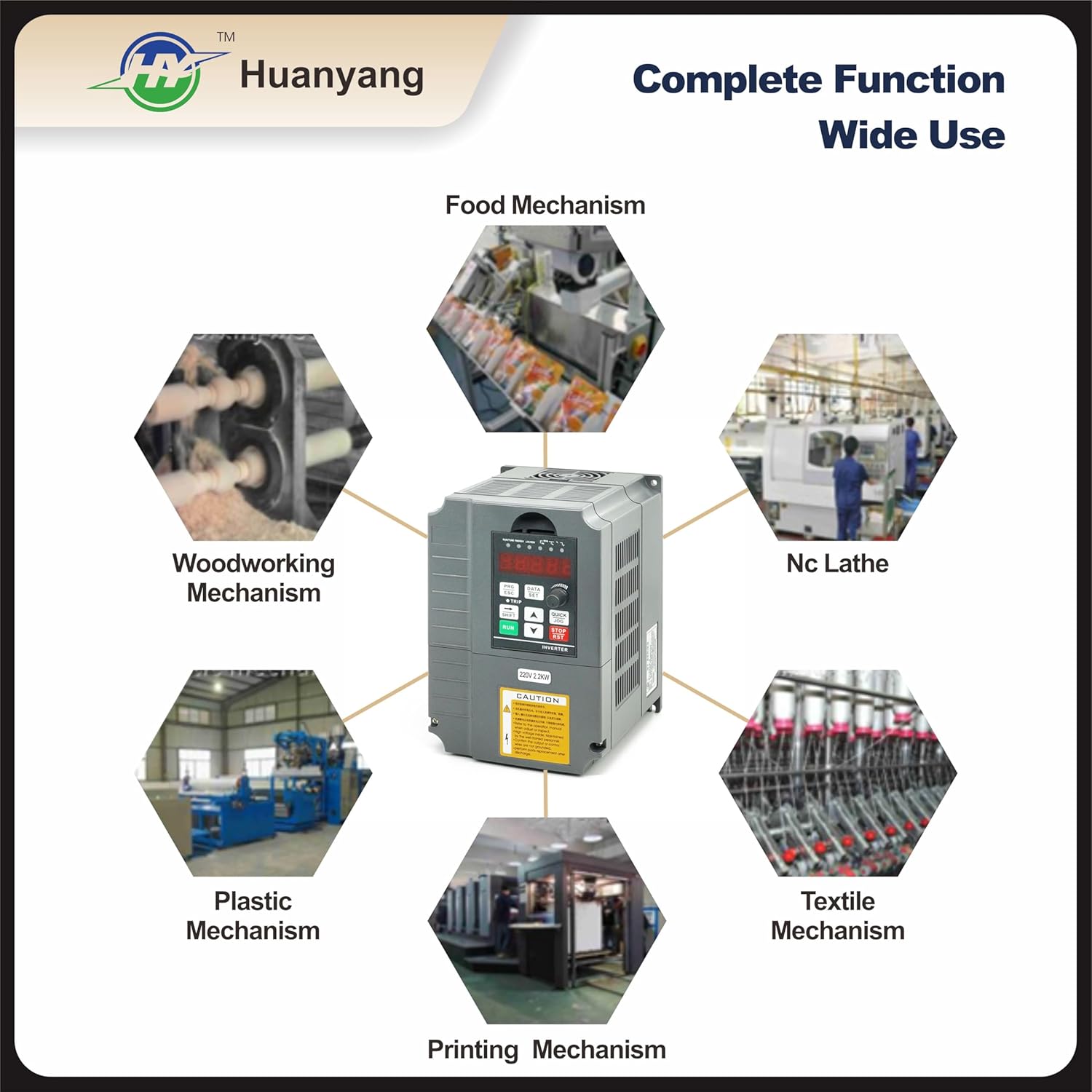
Figure 8: Illustrative diagram showcasing common industrial applications for the VFD, including food mechanisms, woodworking, NC lathes, textile, printing, and plastic mechanisms.
8. Warranty and Support
8.1 Warranty
This HY HUANYANG VFD comes with a 1-year replacement warranty. If you encounter any issues or error codes, please contact our customer service for assistance.
8.2 Customer Support
For technical support, troubleshooting guidance, or warranty claims, please contact HY HUANYANG customer service. Provide your product model number (GT-2R2G-2) and a detailed description of the issue for prompt assistance.