
1. Introduction
The Cwmiibili XY12522 is a CNC DC adjustable stabilized power supply module designed for precise voltage and current regulation. It features a color screen display for easy monitoring and control, supporting a wide input voltage range and high output power. This module is suitable for various applications requiring stable and adjustable power, including laboratory use, electronic development, and solar charging with its MPPT function.

Figure 1: The XY12522 power supply module and its color display unit. The module features large capacitors and inductors for power regulation, while the display shows voltage, current, and power readings with control buttons and a rotary encoder.
2. Key Features
- Wide Input Voltage Range: Supports 12.0V to 140V DC input.
- Adjustable Output: Output voltage from 0.0V to 125V and output current from 0A to 22.00A.
- High Power Output: Capable of delivering up to 2000W.
- Color LCD Display: Large 1.8-inch LCD (38x29mm visible range) for clear display of parameters.
- MPPT Function: Supports Maximum Power Point Tracking for efficient solar charging.
- Serial Communication: Supports standard MODBUS protocol with dual serial ports (TTL and 485 communication).
- Onboard Buzzer: Provides key prompts and alarm notifications.
- High-Precision Clock: External clock crystal oscillator ensures accurate time, capacity, and energy statistics.
- Advanced MCU Controller: 48-pin MCU with 64M frequency for faster operation.
- Multiple Protection Mechanisms: Includes input undervoltage (UVP), output overvoltage (OVP), overcurrent (OCP), overpower (OPP), over-temperature (OTP), over-time (OHP), over-capacity (OAP), and over-energy (OPH) protections.
- Firmware Upgrade Support: Allows for future software enhancements.
- Storage Data Groups: 10 groups for saving frequently used settings.
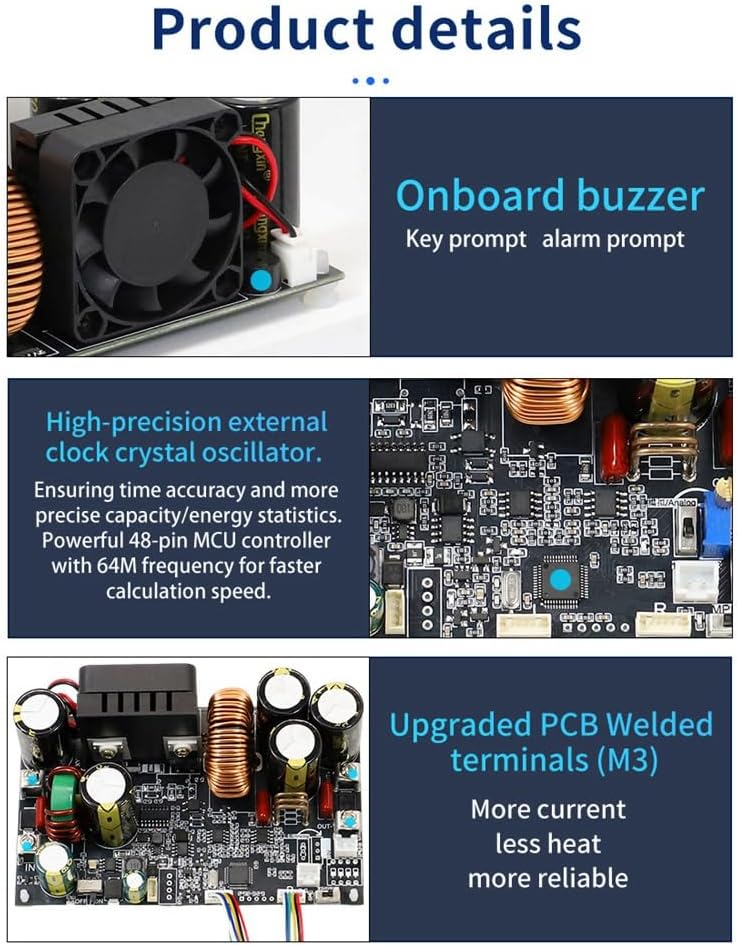
Figure 2: Close-up views highlighting key features such as the onboard cooling fan, high-precision external clock crystal oscillator, and upgraded PCB with welded M3 terminals for improved current handling and reliability.

Figure 3: Diagram illustrating the network control capabilities of the XY12522, showing connectivity options via PC host computer and mobile APP (Sinilink control) for remote operation and monitoring through Sinilink Cloud.
3. Technical Specifications
| Parameter | Value |
|---|---|
| Product Name | CNC DC Step-Down Power Supply |
| Input Voltage | 12.0V - 140V DC |
| Output Voltage | 0.0V - 125V |
| Output Current | 0 - 22.00A |
| Output Power | 2000W (Max) |
| Voltage Resolution | 0.01V |
| Current Resolution | 0.01A |
| Output Ripple (Typical) | 200mV VPP |
| Screen Size | >1.8-inch LCD (38x29mm visible range) |
| Storage Data Groups | 10 groups |
| MPPT Function | Supports MPPT solar charging |
| Product Dimensions (L x W x H) | 7.09 x 3.54 x 2.36 inches |
| Item Weight | 12.1 ounces (343 Grams) |
| Color | Black |
Protection Mechanisms:
- Input Undervoltage Protection (UVP): 10-145V adjustable, default 10V.
- Output Overvoltage Protection (OVP): 0-130V adjustable, default 130V.
- Output Overcurrent Protection (OCP): 0-23A adjustable, default 23A.
- Output Overpower Protection (OPP): 0-2200W adjustable, default 2200W.
- Over-temperature Protection (OTP): 0-110℃ adjustable, default 95℃.
- Over-time Protection (OHP): 1 minute - 99 hours 59 minutes, default off.
- Over-capacity Protection (OAP): 0-9999Ah adjustable, default off.
- Over-energy Protection (OPH): 0-4200KWh adjustable, default off.

Figure 4: Display showing various protection settings such as LVP (Low Voltage Protection), OCP (Over Current Protection), OVP (Over Voltage Protection), and OPP (Over Power Protection). The device offers comprehensive safety features.
4. Package Contents
The standard package for the XY12522 includes:
- 1 x Adjustable Constant Voltage and Constant Current Module (XY12522)
- 1 x Display Unit
Note: Other products shown in promotional images are not included unless explicitly stated.
5. Safety Precautions
Failure to follow these precautions may result in damage to the device, personal injury, or fire.
- Input Power: The input of this device cannot be connected to AC power. Do not connect to 220V AC power under any circumstances.
- Maximum Input Voltage: The maximum input voltage must not exceed 145V DC. It is recommended to operate within 140V DC.
- Polarity: Ensure correct positive and negative pole connections. Reverse polarity connection can damage the device.
- Battery Charging: This product does not have output reverse connection protection. Reversing the positive and negative terminals of a battery will damage the device. Battery charging requires specific professional knowledge. Non-professionals are advised not to charge batteries directly to prevent fire and explosion hazards.
- Temperature Probe: An external temperature probe can be connected for over-temperature protection during charging. Attach the probe to the battery; charging will automatically stop if over-temperature is detected.
- Environment: Operate the device in a well-ventilated area, away from flammable materials, moisture, and extreme temperatures.

Figure 5: Illustration of the MPPT function with a solar panel and the connection of an external temperature probe to a battery. This setup enables safe and efficient solar charging with thermal monitoring.
6. Setup Guide
- Unpack: Carefully remove the power supply module and display unit from their packaging. Inspect for any visible damage.
- Connect Display: Connect the display unit to the main power supply module using the provided ribbon cable. Ensure the connection is secure and correctly oriented.
- Input Power Connection: Connect your DC input power source (e.g., a DC power adapter, battery, or solar panel array) to the "IN+" and "IN-" terminals on the power supply module. Observe correct polarity. Ensure the input voltage is within the 12.0V-140V range.
- Output Load Connection: Connect your load to the "OUT+" and "OUT-" terminals. Ensure the load's voltage and current requirements are within the module's output capabilities (0-125V, 0-22A).
- Optional Temperature Probe: If using the MPPT function for battery charging or if temperature monitoring is desired, connect an NTC temperature probe to the designated interface on the display unit. Place the probe on the object to be monitored (e.g., battery).
- Power On: Once all connections are secure, apply power to the input terminals. The display unit should illuminate.

Figure 6: Close-up of the upgraded display unit, showing the power button with red and green indicator lights, and comfortable silicone buttons. The double-layer buckle design for the circuit board is also visible.
7. Operating Instructions
7.1 Basic Operation
- Power On/Off: Press the "ON/OFF" button on the display unit to toggle the output power. The green indicator light signifies output is ON, red signifies OFF.
- Voltage Setting (V-SET): Press the "V-SET" button. Use the rotary encoder to adjust the desired output voltage. Press the encoder to confirm or move to the next digit.
- Current Setting (I-SET): Press the "I-SET" button. Use the rotary encoder to adjust the desired output current limit. Press the encoder to confirm or move to the next digit.
- Switch Display (SW): Press the "SW" button to cycle through different display modes or parameters.
7.2 Protection Settings
The XY12522 offers various adjustable protection mechanisms. To access and modify these settings, refer to the specific menu navigation instructions provided in the full product manual (if available) or experiment with the "SW" button and rotary encoder to navigate the settings menu.
- UVP (Input Undervoltage Protection): Set the minimum acceptable input voltage.
- OVP (Output Overvoltage Protection): Set the maximum allowed output voltage.
- OCP (Output Overcurrent Protection): Set the maximum allowed output current.
- OPP (Output Overpower Protection): Set the maximum allowed output power.
- OTP (Over-temperature Protection): Set the maximum operating temperature.
- OHP (Over-time Protection): Set a time limit for operation.
- OAP (Over-capacity Protection): Set a maximum output capacity (Ah).
- OPH (Over-energy Protection): Set a maximum output energy (KWh).
7.3 MPPT Function (Solar Charging)
When connecting a solar panel as the input source and an external temperature probe to a battery, the MPPT function can be enabled. This optimizes power extraction from the solar panel to efficiently charge the battery. The display will show a battery icon once connected. Ensure the temperature probe is correctly attached to the battery for over-temperature protection during charging.
7.4 Data Storage
The device supports storing up to 10 groups of settings. Consult the full manual for instructions on how to save and recall these settings.
8. Maintenance
- Cleaning: Regularly clean the exterior of the device with a soft, dry cloth. Do not use abrasive cleaners or solvents. Ensure no dust accumulates in the fan or ventilation openings.
- Ventilation: Ensure the cooling fan and ventilation holes are unobstructed to prevent overheating.
- Storage: When not in use for extended periods, store the device in a cool, dry place, away from direct sunlight and extreme temperatures.
- Firmware Updates: Check the manufacturer's website periodically for firmware updates to ensure optimal performance and access to new features.
9. Troubleshooting
| Problem | Possible Cause | Solution |
|---|---|---|
| Device does not power on. | No input power; incorrect input voltage; reversed input polarity; damaged cable. | Verify input power source is active. Check input voltage is within 12.0V-140V. Ensure correct polarity. Inspect cables for damage. |
| No output voltage/current. | Output is OFF; protection mechanism triggered (OVP, OCP, etc.); incorrect settings. | Press the "ON/OFF" button to enable output. Check display for active protection warnings. Adjust voltage/current settings. |
| Display is blank or erratic. | Loose display cable; power issue. | Ensure the ribbon cable connecting the display to the module is securely seated. Check input power stability. |
| Over-temperature warning. | Insufficient ventilation; excessive load; high ambient temperature. | Ensure fan and vents are clear. Reduce load. Move device to a cooler environment. |
| MPPT not functioning. | Solar panel not connected; MPPT not enabled; insufficient sunlight; temperature probe not connected or faulty. | Verify solar panel connection. Ensure MPPT is enabled in settings. Check sunlight conditions. Confirm temperature probe connection. |
10. Warranty and Support
For warranty information and technical support, please refer to the documentation provided with your purchase or contact Cwmiibili customer service directly. Keep your purchase receipt as proof of purchase for warranty claims.
Manufacturer: Cwmiibili
ASIN: B0F3WSTPC4
Date First Available: April 8, 2025