1. Introduction
This manual provides essential information for the proper installation, operation, and maintenance of your Mechanivis FarDriver Controller ND721200 Encoder BLDC. This high-power controller is designed for electric motorcycle applications, offering robust performance and reliability. Please read this manual thoroughly before using the product to ensure safe and efficient operation.
2. Safety Information
- Always disconnect power before performing any installation, wiring, or maintenance.
- Ensure all wiring connections are secure and correctly polarized to prevent damage to the controller or other components.
- Avoid exposing the controller to extreme temperatures, direct sunlight for prolonged periods, or corrosive environments.
- Do not attempt to open or modify the controller casing, as this will void the warranty and may lead to electrical hazards.
- Consult a qualified technician if you are unsure about any installation or troubleshooting steps.
3. Package Contents
Verify that all items are present and undamaged upon unpacking:
- Mechanivis FarDriver Controller ND721200 Encoder BLDC
- Wiring Harness
- Mounting Screws
- USB Communication Adapter
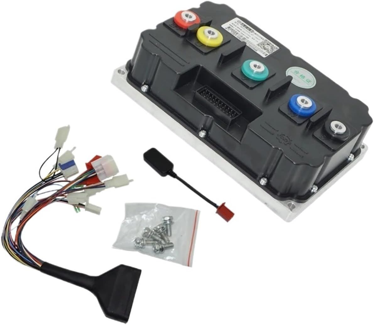
Image 3.1: The FarDriver Controller ND721200 shown with its wiring harness, USB communication adapter, and mounting screws.
4. Product Overview
The FarDriver Controller ND721200 is a high-performance BLDC motor controller featuring an encoder input for precise motor control. Its robust aluminum housing ensures durability and efficient heat dissipation.

Image 4.1: Front view of the controller, highlighting the multi-pin connector for signal and communication wiring.

Image 4.2: Top view of the controller, showing the main power terminals (red, yellow, green, blue) and the signal connector port.
5. Specifications
| Feature | Value |
|---|---|
| Model | ND721200 Encoder |
| Rated Voltage | 72V (Compatible with 84V/96V systems) |
| Max DC Current | 600A |
| Protect Phase Current | 1200A |
| Adaptation Motor Power | 8-12kW |
| Net Weight | 5.1 kg |
| Waterproof Rating | IP67 |
| Dimensions (L x W x H) | 238mm x 155mm x 72.5mm |
| Material | Aluminum |
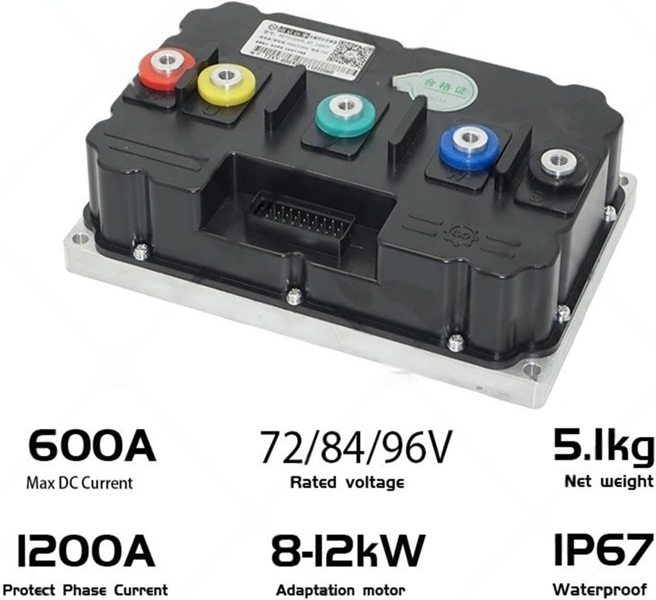
Image 5.1: Visual representation of key specifications including current, voltage, weight, motor power, and IP rating.

Image 5.2: Detailed dimensional drawing of the controller, showing length, width, and height measurements.
6. Setup and Installation
6.1 Mounting the Controller
Select a secure location on your electric motorcycle that provides adequate ventilation and protection from physical impact. Use the provided mounting screws to firmly attach the controller. Ensure the mounting surface is flat to prevent stress on the casing.
6.2 Wiring Connections
Refer to the wiring diagram provided with your specific motor and vehicle for detailed connections. General connections include:
- Battery Power: Connect the main positive and negative terminals from the battery to the corresponding terminals on the controller. Ensure correct polarity.
- Motor Phase Wires: Connect the three phase wires (U, V, W) from the motor to the corresponding terminals on the controller.
- Encoder/Hall Sensor Wires: Connect the encoder or Hall sensor wires from the motor to the designated input on the controller's signal harness.
- Throttle Input: Connect the throttle signal wire to the appropriate input on the signal harness.
- Ignition/Key Switch: Connect the ignition wire to enable/disable the controller.
- Other Signals: Connect brake switches, speed sensors, and other auxiliary signals as required by your system.
Important: Double-check all connections before applying power. Incorrect wiring can cause severe damage.
6.3 Initial Configuration
The controller typically requires initial parameter configuration using dedicated software via the USB communication adapter. This includes setting motor parameters, battery voltage limits, current limits, and throttle response curves. Refer to the software manual for detailed instructions on parameter setup.
7. Operating Instructions
7.1 Power On/Off
Turn the ignition key or switch to the 'ON' position to power on the controller. The system will perform a self-check. To power off, turn the ignition key or switch to the 'OFF' position.
7.2 Throttle Control
Apply throttle gradually to accelerate. The controller will regulate motor speed and power output based on the throttle input and configured parameters. Release the throttle to decelerate.
7.3 Braking
Engaging the brake levers will typically cut power to the motor and activate regenerative braking if configured. Ensure your braking system is fully functional.
8. Maintenance
8.1 Regular Inspection
Periodically inspect the controller and its wiring for any signs of damage, loose connections, or corrosion. Ensure the mounting remains secure.
8.2 Cleaning
Clean the exterior of the controller with a soft, dry cloth. Do not use harsh chemicals or abrasive materials. Ensure no moisture enters the connectors.
8.3 Software Updates
Check with the manufacturer for any available firmware updates that may improve performance or address known issues. Follow update instructions carefully.
9. Troubleshooting
| Problem | Possible Cause | Solution |
|---|---|---|
| Motor does not respond | No power to controller; Loose wiring; Faulty throttle; Motor/encoder issue. | Check battery connection and voltage; Inspect all wiring connections; Test throttle functionality; Check motor and encoder connections. |
| Controller overheats | Excessive load; Insufficient ventilation; Short circuit. | Reduce load; Ensure proper airflow around controller; Check for short circuits in motor or wiring. |
| Erratic motor behavior | Incorrect motor parameters; Damaged encoder/Hall sensor; Signal interference. | Verify motor parameters in software; Inspect encoder/Hall sensor wiring; Check for sources of electromagnetic interference. |
| Controller not communicating with PC | Incorrect USB driver; Faulty USB adapter/cable; Software issue. | Install correct USB drivers; Try a different USB port/cable; Reinstall communication software. |
If problems persist after attempting these solutions, contact customer support for further assistance.
10. Warranty and Support
For warranty information, please refer to the terms and conditions provided at the time of purchase. For technical support, troubleshooting assistance, or spare parts, please contact Mechanivis customer service through your retailer or the official Mechanivis support channels.