
DEWENWILS PTM02
Contents
DEWENWILS 24-Hour Mechanical Timer Switch
Model: PTM02
Heavy Duty, Weatherproof, ETL Listed
1. Introduction
The DEWENWILS PTM02 24-Hour Mechanical Timer Switch is designed for automatic control of heavy-duty electrical loads such as pool pumps, water heaters, lighting, and fans. Its robust metal enclosure and weatherproof design make it suitable for both indoor and outdoor applications. This manual provides essential information for safe installation, operation, and maintenance of your timer switch.
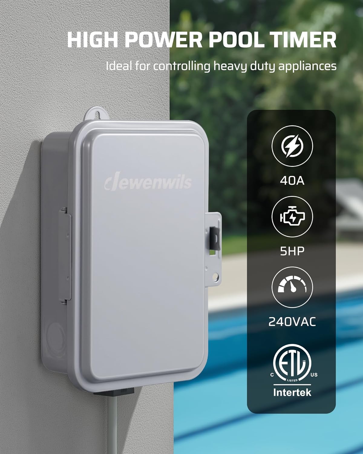
Image 1.1: The DEWENWILS PTM02 Timer Switch, showcasing its high power capacity and suitability for outdoor pool applications.
2. Safety Information
WARNING: Risk of Electric Shock. More than one disconnect switch may be required to de-energize the device before servicing. For supply connections, use copper wire AWG8-14 suitable for 90°C (194°F). Always close the door after use.
- Installation must be performed by a qualified electrician and in accordance with all local and national electrical codes.
- Ensure power is disconnected at the circuit breaker before attempting any installation, wiring, or maintenance.
- Do not immerse the timer in water.
- Verify voltage and current ratings of your load are within the timer's specifications.
- This timer is designed for permanent installation.
3. Package Contents
- DEWENWILS 24-Hour Mechanical Timer Switch (PTM02)
- Installation Screws
- Instruction Manual
4. Specifications
| Feature | Specification |
|---|---|
| Model | PTM02 |
| Switch Type | DPST (Double Pole Single Throw) |
| Input Voltage | 208-277VAC, 60Hz |
| Max Load | 40A Resistive, 5HP |
| Operating Temperature | -40°F to 140°F (-40°C to 60°C) |
| Enclosure Rating | NEMA 3R, IP44 Weatherproof |
| Material | Metal |
| Dimensions (D x W x H) | 4.72" x 6.69" x 7.87" |
| Certifications | ETL Listed |
5. Installation
5.1 Mounting the Enclosure
- Choose a suitable location for mounting, ensuring it is a flat, stable surface and allows for proper wiring access.
- Open the timer enclosure. Use the mounting holes on the back of the enclosure as a template to mark drilling points on the wall.
- Drill pilot holes and secure the enclosure using appropriate screws and anchors (not included).
5.2 Wiring Instructions
IMPORTANT: Ensure all power is OFF at the main circuit breaker before proceeding with wiring.
The PTM02 timer is designed for 208-277VAC applications and can control one 240VAC load or two 120VAC loads. Refer to the internal wiring diagram and the images below for guidance.

Image 5.1: Internal view of the timer switch with wiring diagram.
Wiring for One 240VAC Load:
- Connect the incoming Line 1 (L1) power wire to the terminal labeled 'Line 1'.
- Connect the incoming Line 2 (L2) power wire to the terminal labeled 'Line 2'.
- Connect the Load 1 (L1) wire from your appliance to the terminal labeled 'Load L1'.
- Connect the Load 2 (L2) wire from your appliance to the terminal labeled 'Load L2'.
- Ensure proper grounding according to local codes.

Image 5.2: Wiring diagram for a single 240VAC load.
Wiring for Two 120VAC Loads (e.g., Hot Water Heater):
- Connect the incoming 120VAC Line 1 (L1) power wire to the terminal labeled 'Line 1'.
- Connect the incoming 120VAC Line 2 (L2) power wire to the terminal labeled 'Line 2'.
- Connect the Load 1 (L1) wire from your first 120VAC appliance to the terminal labeled 'Load L1'.
- Connect the Load 2 (L2) wire from your second 120VAC appliance to the terminal labeled 'Load L2'.
- Ensure proper grounding according to local codes.

Image 5.3: Wiring diagram for two 120VAC loads, such as a hot water heater.
After wiring, ensure all connections are secure and close the enclosure door tightly to maintain its weatherproof rating.
6. Operating Instructions
The DEWENWILS PTM02 features a 24-hour mechanical dial for setting ON/OFF times and a manual override switch.

Image 6.1: Detailed view of the timer dial and controls.
6.1 Setting the Current Time
- Rotate the entire dial clockwise until the current time aligns with the 'Current Time' arrow (the small arrow pointing to the dial).
- Ensure AM/PM is correctly set. The dial is marked with AM (Midnight to Noon) and PM (Noon to Midnight) hours.
6.2 Setting ON/OFF Times
The timer uses small, removable trippers around the dial to set ON and OFF times. The white tripper is for ON, and the black tripper is for OFF.
- To set an ON time, push the white tripper into the desired time slot on the dial.
- To set an OFF time, push the black tripper into the desired time slot on the dial.
- You can set up to 2 ON/OFF programs within a 24-hour cycle.
- Once set, the timer will automatically repeat these programs daily.

Image 6.2: Setting the timer by adjusting the dial and trippers.
6.3 Manual Override Switch
The manual override switch allows you to temporarily bypass the set program.

Image 6.3: Manual override switch positions and their functions.
- AUTO: The timer operates according to the set ON/OFF programs. This is the standard operating mode.
- ON (Always ON): The connected device will remain ON, regardless of the set program.
- OFF (Always OFF): The connected device will remain OFF, regardless of the set program.
To return to automatic operation, slide the switch back to the 'AUTO' position.
7. Maintenance
The DEWENWILS PTM02 is designed for durability and minimal maintenance.
- Cleaning: Periodically wipe the exterior of the enclosure with a damp cloth to remove dirt and debris. Do not use abrasive cleaners or solvents.
- Inspection: Regularly inspect the enclosure for any signs of damage, such as cracks or loose seals, which could compromise its weatherproof integrity.
- Weather Protection: Ensure the enclosure door is always securely latched to maintain its IP44 weatherproof rating, protecting internal components from harsh outdoor conditions.

Image 7.1: The timer switch's weatherproof design in an outdoor setting.
8. Troubleshooting
| Problem | Possible Cause | Solution |
|---|---|---|
| Device does not turn ON/OFF at set times. | Incorrect current time setting. Trippers not correctly placed. Manual override switch in ON/OFF position. | Verify current time is aligned with the arrow. Ensure white (ON) and black (OFF) trippers are firmly in place at desired times. Set manual override switch to 'AUTO'. |
| Device is always ON or always OFF. | Manual override switch is engaged. | Slide the manual override switch to the 'AUTO' position. |
| Timer dial is not moving. | No power to the timer. Internal mechanical issue. | Check circuit breaker and wiring connections. If power is present and dial still doesn't move, contact DEWENWILS support. |
| Timer enclosure is wet inside. | Door not properly latched. Damaged seal or enclosure. | Ensure the door is securely closed and latched. Inspect the seal around the door and the enclosure for damage. Replace if necessary. |
9. Warranty and Support
DEWENWILS products are manufactured to high-quality standards. For warranty information, technical support, or assistance with your DEWENWILS 24-Hour Mechanical Timer Switch (Model PTM02), please contact DEWENWILS customer service. Refer to the product packaging or the official DEWENWILS website for contact details.
Ask a question about this manual
Ask about setup, troubleshooting, compatibility, parts, safety, or missing instructions. Manuals+ will review the question and use this page’s manual context to help answer it.