1. Product Overview
The Vernijtrdy XY6506S is an adjustable DC regulated power supply module designed for precise voltage and current control. It features a 1.8-inch high-brightness LCD screen for clear display of parameters and supports various protection functions. This package also includes a K485X communication module for enhanced connectivity.

Figure 1: Vernijtrdy XY6506S Power Supply Module and K485X Communication Module. The image displays the main power supply unit with its screen and control buttons, alongside a smaller K485X communication module connected by a ribbon cable.

Figure 2: Key Features of the XY6506S. This image highlights the 1.8-inch true color LCD screen, input voltage range (12-72V), output voltage range (0-65V), output current range (0-6.000A), 390W output power, and 10 groups of storage space. It also mentions support for standard MODBUS protocol and firmware upgrades.
2. Setup and Connections
Before operating the device, ensure all connections are secure and correct. Refer to the diagram below for typical connection points.
2.1 Power Input
Connect your DC input power source (12V-72V) to the 'VIN+' and 'VIN-' terminals on the module. Observe polarity.
2.2 Power Output
Connect your load to the 'OUT+' and 'OUT-' terminals. Ensure the load's voltage and current requirements are within the module's specifications (0-65V, 0-6A, 390W max).
2.3 K485X Communication Module
The K485X module can be connected for serial communication. Refer to the module's specific documentation for detailed wiring and protocol information.
3. Operating Instructions
The XY6506S features an intuitive interface with a 1.8-inch LCD screen and several control buttons and an encoder knob.
3.1 Controls Overview

Figure 3: Control Buttons and Encoder Functions. This image illustrates the functions of the V-SET, SW, I-SET buttons, the encoder knob, and the ON/OFF switch. V-SET is for setting voltage, I-SET for setting current, SW for shortcut settings and screen rotation, the encoder for shifting and locking, and the ON/OFF button for power output control.
- V-SET Button: Tap to set the output voltage. Press and hold to quickly retrieve data groups.
- I-SET Button: Tap to set the output current. Press and hold to enter or exit the data group page.
- SW Button: Tap to enter shortcut settings. Long press to rotate the screen display in four directions.
- Encoder Knob: Short press to shift between settings. Press and hold to lock the key. Rotate to adjust values.
- ON/OFF Button: Press to enable or disable power output. Press and hold to power off the device.
3.2 Screen Rotation
The device supports a 360° rotatable screen, allowing for optimal viewing from any angle. Long press the 'SW' button to rotate the display orientation.

Figure 4: 360° Screen Rotation. This image shows the power supply module's screen rotating in 90-degree increments, demonstrating its ability to be viewed from any orientation.
3.3 Display Color Customization
The LCD screen supports setting 8 different display colors, allowing users to customize the interface to their preference.

Figure 5: Display Color Customization Options. This image shows various color schemes for the LCD interface, demonstrating the ability to choose from 8 different colors for background and foreground elements.
4. Protection Mechanisms
The XY6506S module incorporates comprehensive protection features to ensure safe operation and protect connected devices.
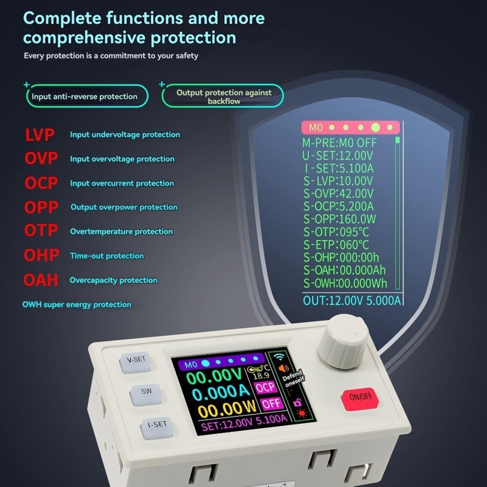
Figure 6: Comprehensive Protection Features. This image lists and visually represents the various protection mechanisms including Input Anti-Reverse Protection, Output Protection Against Backflow, LVP (Input Undervoltage), OVP (Input Overvoltage), OCP (Input Overcurrent), OPP (Output Overpower), OTP (Overtemperature), OHP (Time-out), OAH (Overcapacity), and OWH (Over Energy) protection.
- Input Anti-Reverse Protection: Prevents damage from incorrect input polarity.
- Output Protection Against Backflow: Protects the module from current flowing back from the load.
- LVP (Input Undervoltage Protection): Adjustable from 10-75V, default 10V.
- OVP (Output Overvoltage Protection): Adjustable from 0-67V, default 65V.
- OCP (Output Overcurrent Protection): Adjustable from 0-6.2A, default 6.2A.
- OPP (Output Overpower Protection): Adjustable from 0-400W, default 400W.
- OTP (Overtemperature Protection): Adjustable from 0-110°C, default 95°C.
- OHP (Time-out Protection): Adjustable from 1 minute to 1000 hours. Disabled by default.
- OAH (Over Capacity Protection): Adjustable up to 99999Ah. Disabled by default.
- OWH (Over Energy Protection): Adjustable up to 99999Wh. Disabled by default.
5. MPPT Solar Charging Function
The XY6506S supports MPPT (Maximum Power Point Tracking) solar charging, allowing it to efficiently charge various rechargeable batteries from a solar panel.
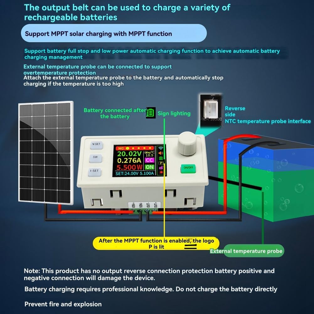
Figure 7: MPPT Solar Charging Connection. This diagram illustrates how to connect a solar panel and a battery to the XY6506S module for MPPT solar charging. It also shows the connection for an external NTC temperature probe for overtemperature protection during charging.
Important Note:
- This product does not have output reverse connection protection for battery positive and negative terminals. Incorrect connection will damage the device.
- Battery charging requires professional knowledge. Do not charge the battery directly without understanding proper procedures.
- Prevent fire and explosion by ensuring correct connections and monitoring.
An external temperature probe can be connected to support overtemperature protection. Attach the external temperature probe to the battery to automatically stop charging if the temperature becomes too high.
6. Specifications
The following table details the technical specifications of the Vernijtrdy XY6506S module:
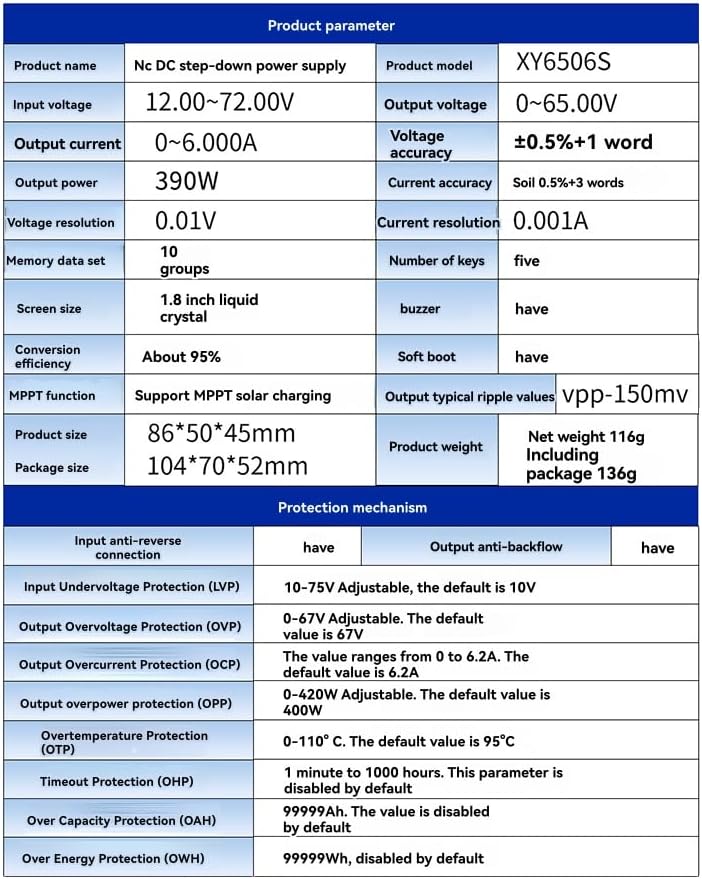
Figure 8: Detailed Product Parameters and Protection Mechanisms. This image presents a table with comprehensive specifications including product name, model, input/output voltage/current, power, accuracy, resolution, memory, screen size, conversion efficiency, MPPT function, product size, package size, weight, and detailed protection mechanism parameters.
| Parameter | Value |
|---|---|
| Product Name | Nc DC step-down power supply |
| Product Model | XY6506S |
| Input Voltage | 12.00 ~ 72.00V |
| Output Voltage | 0 ~ 65.00V |
| Output Current | 0 ~ 6.000A |
| Output Power | 390W |
| Voltage Accuracy | ±0.5% + 1 word |
| Current Accuracy | ±0.5% + 3 words |
| Voltage Resolution | 0.01V |
| Current Resolution | 0.001A |
| Memory Data Sets | 10 groups |
| Number of Keys | Five |
| Screen Size | 1.8 inch liquid crystal |
| Buzzer | Yes |
| Conversion Efficiency | About 95% |
| Soft Boot | Yes |
| MPPT Function | Support MPPT solar charging |
| Output Typical Ripple Values | Vpp-150mV |
| Product Size | 86*50*45mm |
| Package Size | 104*70*52mm |
| Net Weight | 116g |
| Including Package Weight | 136g |
7. Maintenance
To ensure the longevity and proper functioning of your Vernijtrdy XY6506S module, follow these general maintenance guidelines:
- Cleaning: Keep the module clean and free from dust. Use a soft, dry cloth for cleaning. Avoid using liquid cleaners or solvents.
- Environment: Operate the module in a dry, well-ventilated area, away from direct sunlight, excessive heat, and moisture.
- Connections: Periodically check all input and output connections to ensure they are secure and free from corrosion.
- Storage: When not in use for extended periods, store the module in a cool, dry place.
8. Troubleshooting
If you encounter issues with your XY6506S module, consider the following common troubleshooting steps:
- No Power/Display:
- Check the input power supply. Ensure it is within the 12V-72V range and correctly connected.
- Verify the ON/OFF button is pressed to enable output.
- Incorrect Output Voltage/Current:
- Ensure the V-SET and I-SET values are correctly configured.
- Check the load connection. A short circuit or open circuit can affect output.
- Verify that protection features (LVP, OVP, OCP, OPP) are not active, which might limit output.
- Module Overheating:
- Ensure adequate ventilation around the module.
- Reduce the load if it exceeds the module's power rating.
- Check if the OTP (Overtemperature Protection) is triggering.
- Communication Issues (K485X):
- Verify the K485X module is correctly connected and powered.
- Check communication settings (baud rate, parity, etc.) on both the module and the connected device.
If problems persist, consult the manufacturer's support resources.
9. Warranty and Support
For warranty information and technical support, please refer to the documentation provided with your purchase or contact Vernijtrdy customer service through their official channels. Keep your purchase receipt as proof of purchase for warranty claims.