
1. Introduction
The RuoShui VC980+ is a stable and high-performance digital multimeter designed for accurate electrical measurements. Featuring a large 19999-count LCD display with a 42mm-high figure, it ensures clear readability. This instrument incorporates intelligent protection and overload protection, making it a reliable tool for various applications. It is capable of measuring DC voltage (DCV), AC voltage (ACV), DC current (DCA), AC current (ACA), resistance, capacitance, frequency, and includes functions for diode, triode (hFE), and continuity testing. The VC980+ utilizes a dual-integral A/D converter for precision measurements.
2. Safety Information
To ensure safe operation and to avoid damage to the meter, please read this manual carefully before use and observe all safety warnings. Keep this manual for future reference.
- Always ensure the test leads are properly connected and the function switch is set to the correct range before making any measurements.
- Do not apply voltage or current that exceeds the maximum specified limits for each range.
- Exercise extreme caution when working with live circuits. High voltages can be dangerous.
- Do not use the meter if it appears damaged or if the insulation on the test leads is compromised.
- Replace the battery immediately when the low battery indicator appears to ensure accurate readings.
- Always disconnect the test leads from the circuit before changing the function switch.
- The meter is equipped with overload protection. However, avoid intentional overloading.
3. Product Overview
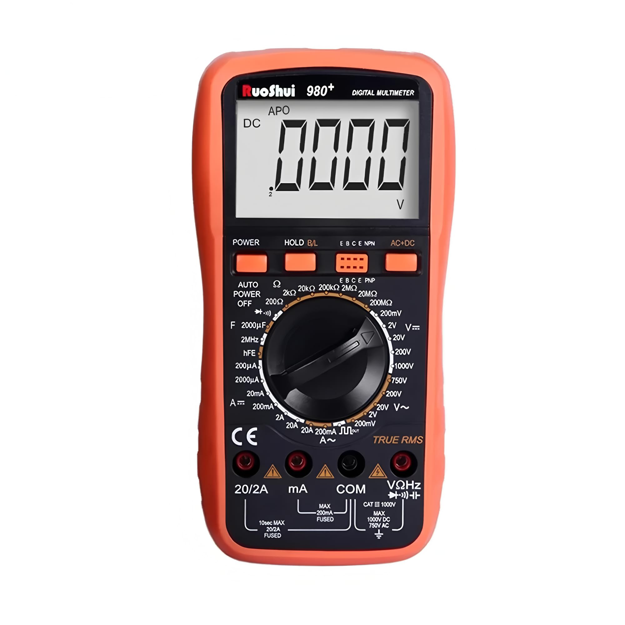
The RuoShui VC980+ Digital Multimeter is designed for versatility and ease of use. Key features include:
- 19999 Display Counts: Provides high resolution for precise measurements.
- True RMS: Accurate measurement of AC voltage and current, especially for non-sinusoidal waveforms.
- Backlight Display: Improves visibility in dimly lit environments.
- Data Hold: Freezes the displayed reading for convenient recording.
- Auto Power Off: Conserves battery life by automatically shutting down after a period of inactivity.
- Low Battery Indication: Alerts the user when the battery needs replacement.
- Over Range Indication: Notifies the user when the measured value exceeds the selected range.
- Overload Protection: Safeguards the meter against damage from excessive input.
- Intelligent Anti-Burn Protection Circuit: Enhances safety and durability.
4. Setup
4.1 Battery Installation
The VC980+ multimeter operates on a 9V battery. To install or replace the battery:
- Ensure the multimeter is powered off and all test leads are disconnected.
- Locate the battery compartment cover on the back of the unit.
- Use a screwdriver to remove the screw securing the battery cover.
- Gently remove the cover.
- Connect a new 9V battery to the battery clip, observing correct polarity.
- Place the battery into the compartment and replace the cover, securing it with the screw.

4.2 Test Lead Connection
Connect the red test lead to the "VΩHz" or "mA" or "20A" input jack, depending on the measurement type. Connect the black test lead to the "COM" (common) input jack for all measurements.
5. Operating Instructions
Before taking any measurement, ensure the meter is set to the correct function and range. Refer to the markings on the rotary switch and the display for guidance.
5.1 Measuring DC Voltage (DCV)
- Set the rotary switch to the "V=" (DCV) range.
- Connect the red test lead to the "VΩHz" jack and the black test lead to the "COM" jack.
- Connect the test probes across the component or circuit to be measured, observing polarity.
- Read the voltage value on the display.
5.2 Measuring AC Voltage (ACV)
- Set the rotary switch to the "V~" (ACV) range.
- Connect the red test lead to the "VΩHz" jack and the black test lead to the "COM" jack.
- Connect the test probes across the component or circuit to be measured.
- Read the voltage value on the display.
5.3 Measuring DC Current (DCA)
- Set the rotary switch to the "A=" (DCA) range (e.g., 200mA, 20A).
- For currents up to 200mA, connect the red test lead to the "mA" jack. For currents up to 20A, connect the red test lead to the "20A" jack. Connect the black test lead to the "COM" jack.
- Caution: To measure current, the meter must be connected in series with the circuit. Never connect the meter in parallel across a voltage source when measuring current, as this can blow the fuse or damage the meter.
- Open the circuit where current is to be measured and insert the meter in series.
- Read the current value on the display.
5.4 Measuring AC Current (ACA)
- Set the rotary switch to the "A~" (ACA) range (e.g., 200mA, 20A).
- Connect the red test lead to the appropriate current jack ("mA" or "20A") and the black test lead to the "COM" jack.
- Caution: Connect the meter in series with the circuit.
- Open the circuit and insert the meter in series.
- Read the current value on the display.
5.5 Measuring Resistance (Ω)
- Set the rotary switch to the "Ω" (Resistance) range.
- Connect the red test lead to the "VΩHz" jack and the black test lead to the "COM" jack.
- Ensure the circuit or component is de-energized before measuring resistance.
- Connect the test probes across the component.
- Read the resistance value on the display.
5.6 Measuring Capacitance (F)
- Set the rotary switch to the "F" (Capacitance) range.
- Connect the red test lead to the "VΩHz" jack and the black test lead to the "COM" jack.
- Ensure the capacitor is fully discharged before measurement to prevent damage to the meter.
- Connect the test probes across the capacitor.
- Read the capacitance value on the display.
5.7 Measuring Frequency (Hz)
- Set the rotary switch to the "Hz" (Frequency) range.
- Connect the red test lead to the "VΩHz" jack and the black test lead to the "COM" jack.
- Connect the test probes across the signal source.
- Read the frequency value on the display.
5.8 Diode Test
- Set the rotary switch to the "Diode" symbol.
- Connect the red test lead to the "VΩHz" jack and the black test lead to the "COM" jack.
- Connect the red probe to the anode and the black probe to the cathode of the diode.
- The display will show the forward voltage drop. Reverse the probes; the display should show "OL" (open loop) for a good diode.
5.9 Continuity Test
- Set the rotary switch to the "Continuity" symbol (often shared with resistance or diode).
- Connect the red test lead to the "VΩHz" jack and the black test lead to the "COM" jack.
- Connect the test probes across the circuit or component.
- If the resistance is below a certain threshold (typically <50Ω), the buzzer will sound, indicating continuity. The display will also show the resistance value.
5.10 hFE Test (Transistor Test)
- Set the rotary switch to the "hFE" position.
- Insert the transistor leads (Emitter, Base, Collector) into the corresponding holes in the hFE socket on the meter, ensuring correct NPN or PNP type selection.
- Read the hFE (DC current gain) value on the display.
6. Maintenance
6.1 Battery Replacement
When the "BAT" symbol appears on the display, the battery voltage is low and needs to be replaced. Follow the steps outlined in Section 4.1 Battery Installation.
6.2 Fuse Replacement
If the current measurement function fails, the fuse may be blown. To replace the fuse:
- Ensure the multimeter is powered off and all test leads are disconnected.
- Remove the battery compartment cover and the battery.
- Carefully open the back casing of the multimeter (this may require removing additional screws).
- Locate the blown fuse(s). The VC980+ typically uses a 250mA fuse for lower current ranges and a 20A fuse for higher current ranges.
- Replace the blown fuse with a new fuse of the exact same type and rating. Using an incorrect fuse can damage the meter or pose a safety hazard.
- Reassemble the casing and battery cover.

6.3 Cleaning
Wipe the case with a damp cloth and mild detergent. Do not use abrasives or solvents. Keep the input terminals free from dirt and moisture.
7. Troubleshooting
| Problem | Possible Cause | Solution |
|---|---|---|
| No display or faint display | Low or dead battery | Replace the 9V battery (refer to Section 4.1). |
| Incorrect readings | Incorrect function/range selected; poor test lead connection; low battery | Verify function and range; ensure leads are firmly connected; replace battery. |
| Current measurement not working | Blown fuse; incorrect connection (not in series) | Check and replace fuse (refer to Section 6.2); ensure meter is connected in series. |
| "OL" (Overload) displayed | Measured value exceeds selected range; open circuit (for continuity/resistance) | Select a higher range; check for open circuit in the component/wire. |
| No continuity beep | Open circuit; resistance too high | Check the circuit for breaks; ensure resistance is below the continuity threshold. |
8. Specifications
The following table details the general and measurement specifications for the RuoShui VC980+ Digital Multimeter.
| Feature | Specification |
|---|---|
| Display Counts | 19999 |
| True RMS | Yes |
| Backlight Display | Yes |
| Data Hold | Yes |
| Auto Power Off | Yes |
| Low Battery Indication | Yes |
| Over Range Indication | Yes |
| Overload Protection | Yes |
| Diode Test | Yes |
| hFE Test | Yes |
| Continuity Test | Yes |
| Power Source | 9V Battery (Battery Powered) |
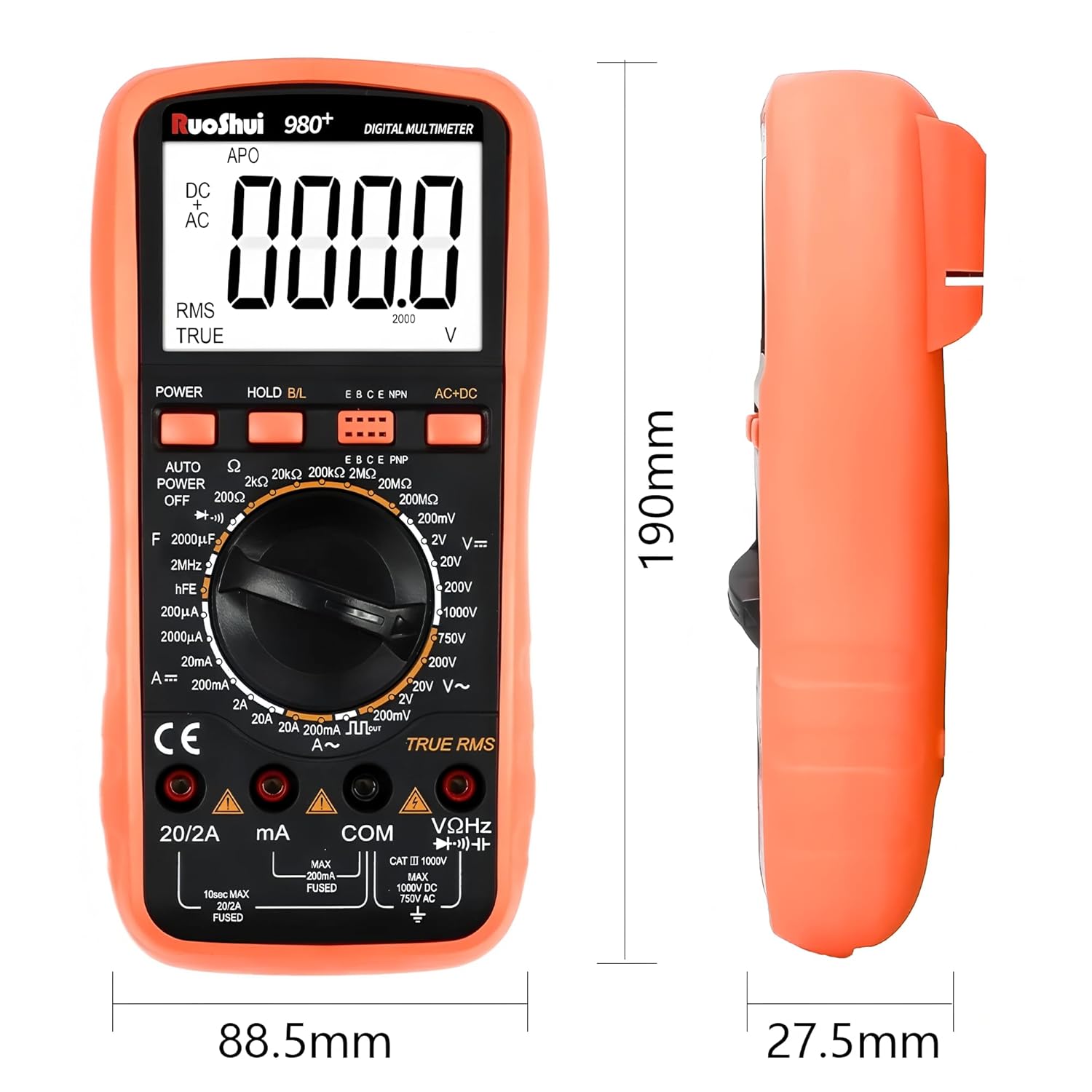
| Dimensions (L x W x H) | 7.87 x 5.91 x 7.09 inches (approx. 190 x 88.5 x 27.5 mm) |
| Item Weight | 2.2 pounds (approx. 1 Kilogram) |
| Operating Temperature | Up to 60 Degrees Celsius |
| Certifications | CE, RoHS, UL |
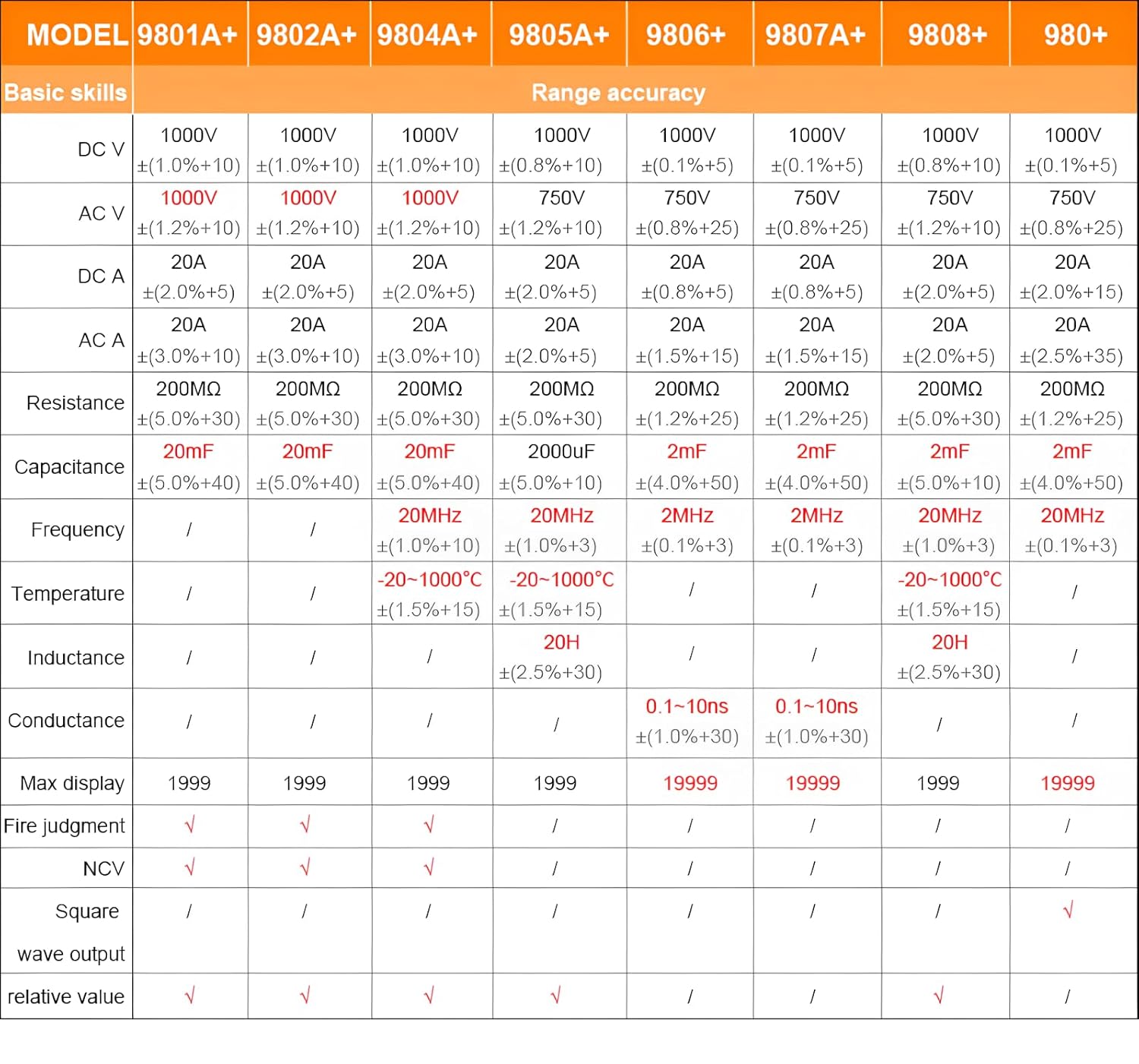
For detailed range accuracy, please refer to the following table:
9. Warranty and Support
The RuoShui VC980+ Digital Multimeter is manufactured by Xi'an Beicheng Electronics Co.Ltd (RUOSHUI). For support or warranty inquiries, please contact the manufacturer or your point of purchase. EU spare part availability duration is 1 year.
For further assistance, please visit the official RuoShui store or contact customer service through the retailer where the product was purchased.


