1. Product Overview
The eletechsup DD39AJPA- is a versatile 20W DC-DC Boost-Buck Converter Module designed to provide adjustable positive and negative dual output voltages from a single positive input. It features high efficiency and built-in protection functions, making it suitable for various electronic applications.
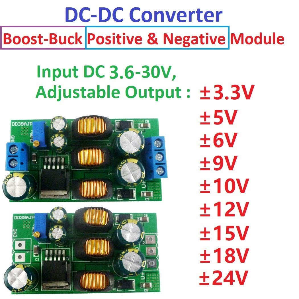
Image 1: DC-DC Boost-Buck Converter Module with adjustable output ranges. This image highlights the various adjustable positive and negative output voltages from ±3.3V to ±24V.
2. Specifications
| Feature | Description |
|---|---|
| Input Voltage | 3.6V to 30V DC |
| Output Voltage | ±3V to ±30V DC (Adjustable) |
| Maximum Output Power | 20W |
| Conversion Efficiency | 69% - 88% |
| Quiescent Current | 3mA |
| Working Frequency | 180KHz |
| Operating Temperature | -40°C to +85°C |
| Dimensions | 60 x 34 x 15mm |
| Weight | 33g (with terminal), 29g (no terminal) |
| Built-in Features | Frequency Compensation, Soft-Start Function, Thermal Shutdown Function, Current Limit Function |

Image 2: Module Dimensions and Weight. This image displays the physical size (60 x 34 x 15mm) and weight (33g with terminal) of the converter module.

Image 3: Top view of the eletechsup DD39AJPA- module with terminals, showing component layout.

Image 4: Side view of the eletechsup DD39AJPA- module with terminals, highlighting the height and component arrangement.
3. Setup and Wiring
3.1. Application 1: Positive and Negative Dual Output
This configuration provides both positive (V+) and negative (V-) output voltages from a single positive input. It is crucial that the negative voltage (V-) is not used alone. When using V-, a load must also be connected to the positive voltage (V+) terminal.

Image 5: Application 1: Input positive voltage, output positive and negative voltage. This diagram illustrates the wiring for a dual positive and negative output configuration. Note that negative voltage cannot be used separately.
3.2. Application 2: Positive Output Only
This configuration provides only a positive (V+) output voltage from a single positive input. The V- terminal is not utilized in this setup.

Image 6: Application 2: Input positive voltage, output positive voltage. This diagram shows the wiring for a single positive output configuration.
3.3. Output Voltage Adjustment
The output voltage (both positive and negative) can be adjusted using the onboard potentiometer. Carefully turn the potentiometer with a small screwdriver to set the desired output voltage within the specified range.
4. Operating Guidelines
- Stable Voltage Output: For more stable voltage output, it is recommended that the output current is greater than 15mA.
- Startup Current: The startup current of the module is typically 2.5-3 times the operating current.
- Reducing Startup Current: Increasing the capacitance by adding a 1UF-10UF MLCC capacitor can help reduce the startup current. Refer to the image below for placement.
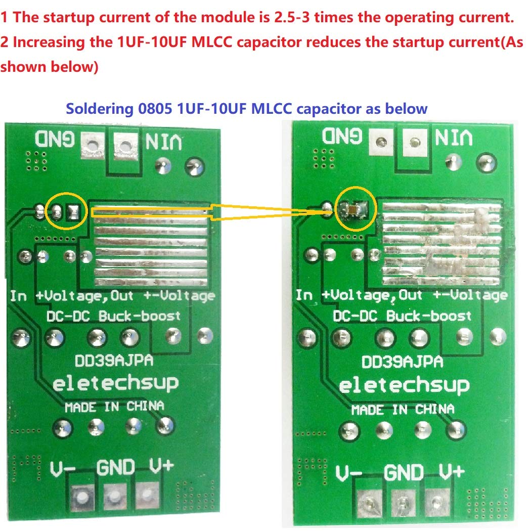
Image 7: Illustration of soldering a 1UF-10UF MLCC capacitor to reduce startup current. The image shows the top and bottom views of the PCB with the recommended capacitor placement.
5. Important Notes and Warnings
- The input voltage must not exceed the maximum input range of 30V.
- The output power should not exceed the maximum load of 20W for extended periods.
- The input power must always be greater than the output power, accounting for the module's internal power consumption.
- The negative voltage (V-) cannot be used independently. If a negative voltage is required, a corresponding load must also be connected to the positive voltage (V+) terminal.
6. Troubleshooting
6.1. Output Voltage is Less Than Nominal
Issue: The measured output voltage is lower than the expected or set nominal voltage.
Solution: This often indicates that the input power supply is insufficient. Use a multimeter to check the input voltage; it may be too low under load. Ensure your input power source can provide adequate current and voltage for the desired output.
6.2. No Negative Voltage Output or Output Too Low
Issue: The negative voltage (V-) is not present or is significantly lower than expected.
Solution: The negative voltage output cannot be used alone. When utilizing the negative voltage, a load must also be connected to the positive voltage (V+) terminal. Ensure both positive and negative outputs have appropriate loads connected.
7. Applications
This DC-DC Boost-Buck Converter Module is suitable for a wide range of applications, including:
- ADC/DAC/Operational Amplifier power supplies
- RS232, RS485, RS422 Bus systems
- Audio equipment and low-power audio power supplies
- Car audio amplifier dual power boards
- LCD power supplies
- Instrumentation equipment and multimeters
8. Maintenance
The eletechsup DD39AJPA- module is designed for reliable operation and typically requires no specific user maintenance. Ensure proper ventilation and keep the module free from dust and moisture to prolong its lifespan.


