Introduction
Thank you for choosing the BESTTEN Super Slim Dimmer Switch. This manual provides detailed instructions for the safe installation, operation, and maintenance of your new dimmer switch. Please read all instructions carefully before installation and retain this manual for future reference.

Image: Six BESTTEN Super Slim Dimmer Switches.
Safety Information
- WARNING: To avoid fire, shock, or death, turn off power at the circuit breaker or fuse box and test that the power is off before wiring.
- Install in accordance with all national and local electrical codes.
- Use only copper wire.
- This device is for indoor use only.
- Do not use with non-dimmable bulbs.
- Maximum load: 300W for dimmable LED/CFL, 600W for incandescent/halogen.
- Only one dimmer switch can be installed per 3-way circuit.
Package Contents
- BESTTEN Super Slim Dimmer Switch (Quantity as purchased, e.g., 6 switches)
- Mounting Screws
Note: Wall plates are not included and must be purchased separately.
Specifications
| Parameter | Value |
|---|---|
| Voltage | 120V, 60Hz |
| Dimmable LED/CFL Max. Load | 300W |
| Incandescent/Halogen Max. Load | 600W |
| Switch Type | Single Pole / 3-Way |
| Wiring Type | Wire Pigtails |
| Operation Temperature | 32°F – 104°F (0°C – 40°C) |
| Certifications | ETL/cETL Listed |
| Dimensions (L x W x H) | 4.13 x 1.73 x 0.87 inches |

Image: Detailed specifications for the dimmer switch.

Image: Super Slim Design dimensions.

Image: Bulb compatibility and wattage ratings.
Setup and Installation
Before beginning installation, ensure the power is turned off at the circuit breaker. This dimmer switch is designed for both single-pole and 3-way applications and does not require a neutral wire, making it suitable for older electrical systems.

Image: No neutral wire required feature.
Wiring Instructions
- Turn off power: Locate your circuit breaker or fuse box and turn off the power to the switch location. Verify power is off using a voltage tester.
- Remove existing switch: Carefully remove the old switch from the wall box.
- Identify wires: Identify the Line (Hot), Load, Ground, and Traveler wires (for 3-way installations). It is recommended to take a picture of the existing wiring before disconnecting.
- Connect wires: Refer to the wiring diagrams below for single-pole and 3-way installations. Use wire nuts to secure connections.
- Black wire: Connect to the Line (Hot) wire.
- Red wire: Connect to the Load wire.
- Green wire: Connect to the Ground wire.
- Red & White wire: This wire is used only in 3-way installations. For single-pole installations, cap this wire with a wire nut. In 3-way installations, connect it to one of the Traveler wires.
- Mount the dimmer: Gently push the wired dimmer switch into the wall box and secure it with the provided screws.
- Install wall plate: Attach your desired wall plate (not included).
- Restore power: Turn the power back on at the circuit breaker.

Image: Single Pole and 3-Way Wiring Diagrams.
Important for 3-Way Applications
For 3-way switches, there are three terminals besides the ground. One terminal is typically a different color than the other two. Label this wire as the Line/Load. The other two terminals connect to the Traveler wires. Caution: Only one dimmer switch can be installed in a 3-way circuit.
Operating Instructions
The BESTTEN Super Slim Dimmer Switch features a rocker switch for ON/OFF control and a slide dimmer for brightness adjustment.
- Turning ON/OFF: Press the bottom part of the rocker switch to turn the lights ON, and the top part to turn them OFF.
- Adjusting Brightness: Use the vertical slider on the side of the rocker switch to adjust the light level. Slide up for brighter light and down for dimmer light.
Dimming Range Setting (Sensitivity Dial)
To optimize performance and eliminate flickering with certain bulb types, you may need to adjust the dimmer's sensitivity dial. This small dial is located on the side of the dimmer switch, accessible after removing the wall plate.
- Turn on the switch and move the slide dimmer to its lowest (all the way down) setting.
- Rotate the Sensitivity Dial clockwise all the way down. NOTE: If the dial stops in either direction, do not continue to turn it.
- Rotate the Sensitivity Dial counter-clockwise slowly until the preferred lowest light level is achieved and the lights are not flickering.
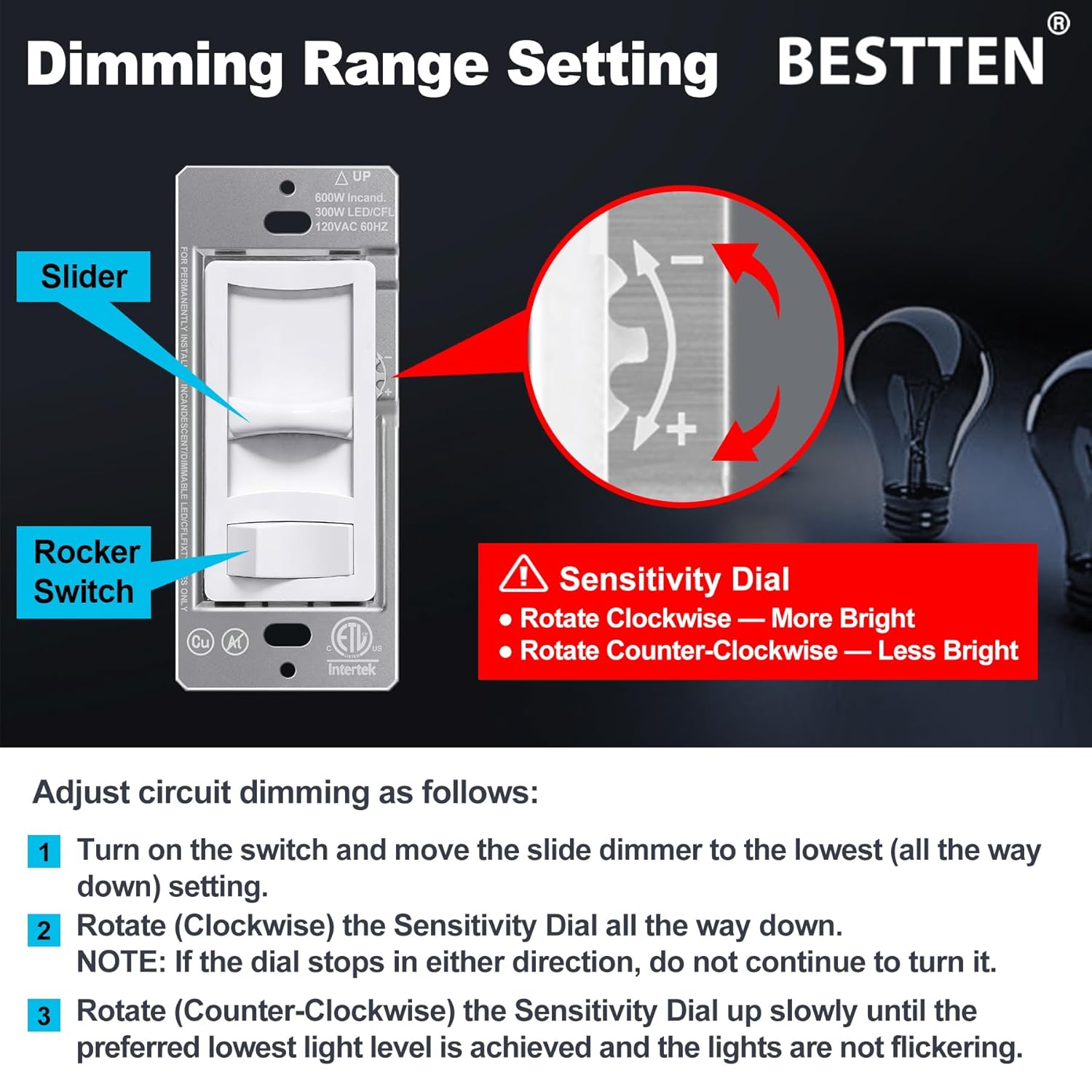
Image: Dimming Range Setting with Sensitivity Dial.
Maintenance
To maintain your dimmer switch, ensure power is off before cleaning. Wipe the surface with a soft, damp cloth. Do not use abrasive cleaners or solvents, as these can damage the finish or internal components. Regular inspection for loose connections or damage is recommended.
Troubleshooting
- Lights do not turn ON:
- Check the circuit breaker and ensure power is restored.
- Verify all wire connections are secure.
- Ensure the bulb is functional and correctly installed.
- Lights flicker, hum, or buzz:
- Adjust the dimming range using the sensitivity dial as described in the 'Operating Instructions' section.
- Ensure your bulbs are specifically rated as 'dimmable'. Non-dimmable bulbs will not function correctly with a dimmer.
- Some dimmable LED/CFL bulbs may not be fully compatible with all dimmers. Consider trying a different brand or type of dimmable bulb.
- Ensure the total wattage of connected bulbs does not exceed the dimmer's maximum load capacity.
- Dimmer switch is warm to the touch:
- It is normal for dimmer switches to feel warm during operation. If the dimmer feels excessively hot, ensure the load does not exceed the maximum wattage rating.

Image: Information on eliminating flickering.
Warranty and Support
BESTTEN products are designed for reliability and performance. For warranty information or technical support, please refer to the manufacturer's official website or contact their customer service directly. Keep your purchase receipt as proof of purchase.
You can find more information and contact details by visiting the BESTTEN Store on Amazon.


