1. Introduction
This manual provides comprehensive instructions for the proper use, setup, operation, and maintenance of the MakerHawk TOFSense-F2 Lidar Sensor. Please read this manual thoroughly before operating the device to ensure optimal performance and safety.
2. Product Overview
2.1 Key Features
- High-Precision Measurement: Offers a range of 0.05-25m with an accuracy of ±3.0cm.
- Fast Refresh Rate: 100Hz refresh frequency for dynamic environments.
- Compact and Lightweight: Weighs 7.5g, dimensions 22.7 x 28 x 13.6mm.
- Versatile Communication Interfaces: Supports UART, IIC, and I/O.
- Robust Interference Resistance: Designed with anti-interference algorithms and optimized optics for stable performance in challenging conditions (ambient light, dust, fog).
2.2 Components Included
- TOFSense-F2 Lidar Sensor Ranging Module
- Connection Cable (4-wire JST style 1.25mm connector, 20cm)

Figure 1: TOFSense-F2 Lidar Sensor and included connection cable. The sensor is a compact black module with an optical lens, and a 4-wire cable is shown below it.
3. Specifications
| Parameter | Value |
|---|---|
| Model Number | TOFSense-F2 |
| Measurement Range | 0.05 - 25 meters |
| Accuracy | ±3.0 cm |
| Refresh Frequency | 100 Hz |
| Field of View (FOV) | 1-2 degrees |
| Power Consumption | 250 mW |
| Anti-Glare Capability | Up to 100Klux |
| Dimensions (L x W x H) | 22.7 x 28 x 13.6 mm |
| Weight | 7.5 g (sensor only), 12.3 g (item weight including cable) |
| Communication Interfaces | UART, IIC, I/O |
| Connector Type | Plug-In (4-wire JST 1.25mm) |

Figure 2: Visual representation of key TOFSense-F2 specifications including accuracy, range, power consumption, refresh rate, FOV, and anti-glare.
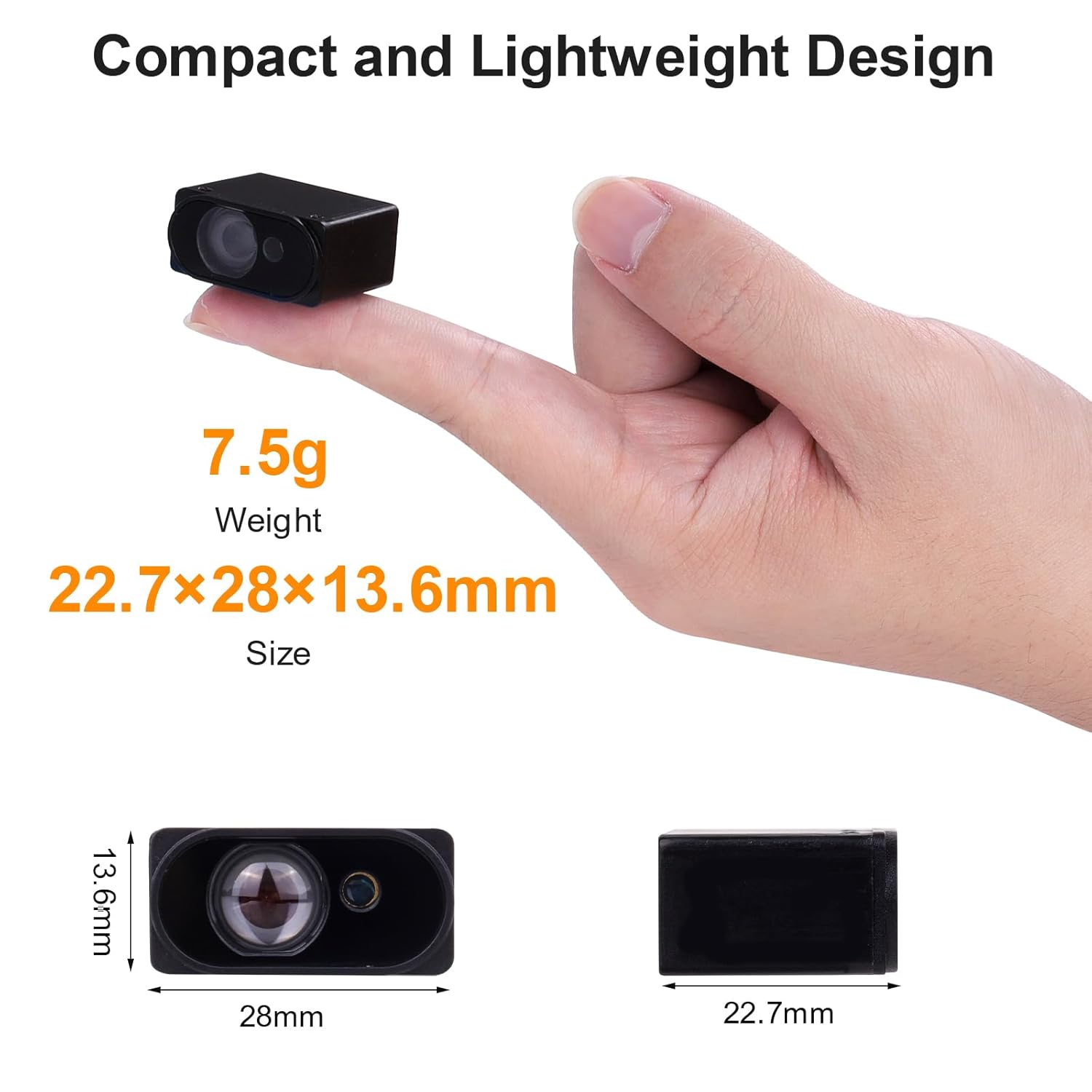
Figure 3: The TOFSense-F2 sensor held between two fingers, illustrating its compact size and lightweight design. Dimensions are shown as 22.7mm x 28mm x 13.6mm.
4. Setup and Connection
4.1 Pin Definition
The TOFSense-F2 module uses a 4-pin connector for power and communication. Refer to the table below for pin definitions:
| Pin Number | Definition |
|---|---|
| PIN 1 | UART_TX / IIC_SCL / IO_L |
| PIN 2 | UART_RX / IIC_SDA / IO_H |
| PIN 3 | GND (Ground) |
| PIN 4 | VCC (Power Supply) |

Figure 4: The connector port of the TOFSense-F2 sensor, showing the 4 pins and their corresponding functions for UART, I2C, and I/O communication.
4.2 Connecting to a Host Device
Connect the TOFSense-F2 sensor to your host device (e.g., Arduino, Raspberry Pi, Pixhawk) using the provided 4-wire cable according to the pin definitions. Ensure correct voltage supply (VCC) and ground (GND) connections to prevent damage.
- UART Connection: Connect PIN 1 (TX) to the host's RX, and PIN 2 (RX) to the host's TX.
- IIC (I2C) Connection: Connect PIN 1 (SCL) to the host's SCL, and PIN 2 (SDA) to the host's SDA.
- I/O Connection: Use PIN 1 (IO_L) and PIN 2 (IO_H) for digital input/output as required by your application.
Caution: Incorrect wiring can damage the sensor or the host device. Always verify pin assignments before applying power.
5. Operating Instructions
5.1 Distance Measurement Principle
The TOFSense-F2 operates on the Time-of-Flight (ToF) principle. It emits a light pulse and measures the time it takes for the pulse to travel to an object and reflect back to the sensor. This time difference is then used to calculate the distance to the object.

Figure 5: Diagram illustrating the Time-of-Flight (ToF) distance measurement principle. An emitted light pulse travels from the sensor to an object, reflects, and returns to the sensor, allowing distance calculation.
5.2 Communication Protocols
The sensor supports UART, IIC, and I/O communication. Detailed protocol specifications and example code for integration with common platforms (e.g., Arduino, Raspberry Pi, Pixhawk) can typically be found on the manufacturer's website or relevant open-source communities (e.g., Ardupilot.org for Pixhawk).
- UART: Standard serial communication. Configure baud rate, data bits, parity, and stop bits as per sensor documentation.
- IIC (I2C): Two-wire serial interface. The default I2C address is 0x08.
- I/O: For simple digital signaling or control.
5.3 Environmental Considerations
The TOFSense-F2 is designed with robust anti-interference capabilities, including resistance to ambient light (up to 100Klux), dust, and fog. However, extreme conditions may still affect performance. Ensure the optical lens is clear and unobstructed for accurate readings.

Figure 6: Illustration highlighting the TOFSense-F2's robust anti-interference features, including anti-glare, dust-proof, and anti-fog capabilities, ensuring stable operation in challenging environments.
6. Applications
The TOFSense-F2 Lidar Sensor is suitable for a wide range of applications due to its precision, speed, and compact design:
- Drone Altitude Hold: Precise height measurement for stable flight.
- Robot Obstacle Avoidance: Detecting objects in the path of autonomous robots.
- Stacking Detection: Monitoring material levels in industrial settings.
- Personnel Detection: Presence sensing in smart traffic systems or security.
- Smart Traffic Systems: Vehicle detection and traffic flow monitoring.
- Intelligent Gesture Control: Non-contact interaction.

Figure 7: Collage of images depicting various applications for the TOFSense-F2 sensor, including drone altitude hold, robot obstacle avoidance, stacking detection, personnel detection, smart traffic systems, and intelligent gesture control.
7. Troubleshooting
- No Readings / Inaccurate Readings:
- Check all wiring connections for proper pin assignment and secure contact.
- Ensure the sensor lens is clean and free from dust or obstructions.
- Verify power supply voltage is within the specified operating range.
- Confirm communication protocol settings (baud rate for UART, I2C address for IIC) match the sensor's configuration.
- Test in different lighting conditions to rule out extreme ambient light interference, although the sensor has high resistance.
- Sensor Not Detected by Host:
- Double-check power and ground connections.
- Ensure the correct communication interface (UART/IIC) is selected and configured on both the sensor and the host.
- For I2C, confirm the address (0x08 default) is not conflicting with other devices on the bus.
- Intermittent Readings:
- Check for loose connections or damaged cables.
- Ensure the target object is within the specified measurement range (0.05-25m).
- Minimize vibrations or rapid movements of the sensor or target if not accounted for in the application logic.
8. Maintenance
- Cleaning: Regularly inspect the optical lens for dust, dirt, or smudges. Clean gently with a soft, lint-free cloth. Avoid abrasive materials or harsh chemicals.
- Storage: Store the sensor in a dry, dust-free environment when not in use.
- Handling: Handle the sensor with care to avoid physical damage. Do not expose to excessive force, extreme temperatures, or moisture.
- Firmware Updates: Check the manufacturer's website for any available firmware updates that may improve performance or add features. Follow update instructions carefully.


