1. Introduction
The KZ35 35W USB Electronic Load Tester is a versatile device designed for testing battery voltage, capacity, and charger performance. It features adjustable constant current, intelligent temperature control, and support for various fast charging protocols. This manual provides detailed instructions for its setup, operation, and advanced settings.

Figure 1.1: KZ35 35W USB Electronic Load Tester with fan and display.
2. Key Features
- KZ35 35W QC2.0 QC3.0 USB Electronic Load Adjustable Constant Current Aging Resistor Battery Voltage Capacity Tester Voltmeter
- Intelligent temperature control fan + All aluminum fan for efficient heat dissipation
- Quick charge trigger modes: QC2.0 (5V, 9V, 12V, 20V), QC3.0, AFC9V, FCP
- Rated operational current: 0.03-5.00A (Fan starts tuning at 0.22A)
- Rated operational voltage: DC4.0-25.0V (Features reverse solution protection)
3. Product Components and Interfaces
The KZ35 tester is equipped with multiple interfaces and controls for comprehensive testing.
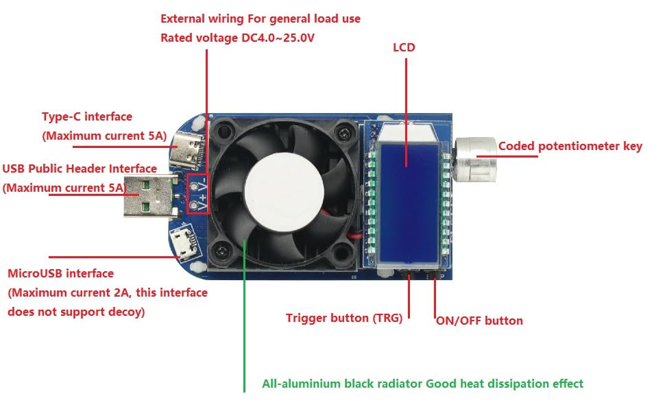
Figure 3.1: Labeled diagram of the KZ35 Electronic Load Tester's interfaces and components.
- USB Public Header Interface: Standard USB-A input, maximum current 5A.
- Type-C Interface: USB-C input, maximum current 5A.
- MicroUSB Interface: Micro-USB input, maximum current 2A. Note: This interface does not support decoy (fast charge triggering).
- External Wiring: Terminals for general load use, rated voltage DC4.0-25.0V.
- LCD: Liquid Crystal Display for real-time data and settings.
- Coded Potentiometer Key: Rotary encoder for navigation and adjustment, with a push-button function.
- ON/OFF Button: Controls the electronic load's on/off state and data lock.
- Trigger Button (TRG): Used for fast charge protocol selection and detection.
- All-aluminium Black Radiator: Integrated heat sink for effective heat dissipation.
4. Setup and Basic Operation
4.1 Initial Setup
Connect the KZ35 tester to a power source or device under test using one of the input interfaces (USB-A, Type-C, MicroUSB, or external wiring terminals). The LCD will power on and display the operating interface.
4.2 Operating Interface Instructions

Figure 4.1: KZ35 display showing real-time voltage and protocol trigger options.
- Power On/Off and Current Adjustment: After powering on, short press the "ON/OFF" button to turn the electronic load on or off. Rotate the encoder potentiometer to modify the current of the electronic load in real-time.
- Toggle Downlink Display: Short press the encoding potentiometer key to cycle through the downlink display content: current, power, capacity, and time.
- Automatic Display Switch: In any display interface, rotating the encoding potentiometer will automatically switch to the current display interface.
- Data Lock Function: In the current display interface, long press the "ON/OFF" button to toggle the data lock function. When activated, a locking symbol "|-" will appear before the current, preventing accidental current adjustments via the encoder.
- Clear Capacity/Time Data: In the Capacity/Time interface, long press the "ON/OFF" button to clear the corresponding capacity or time data.
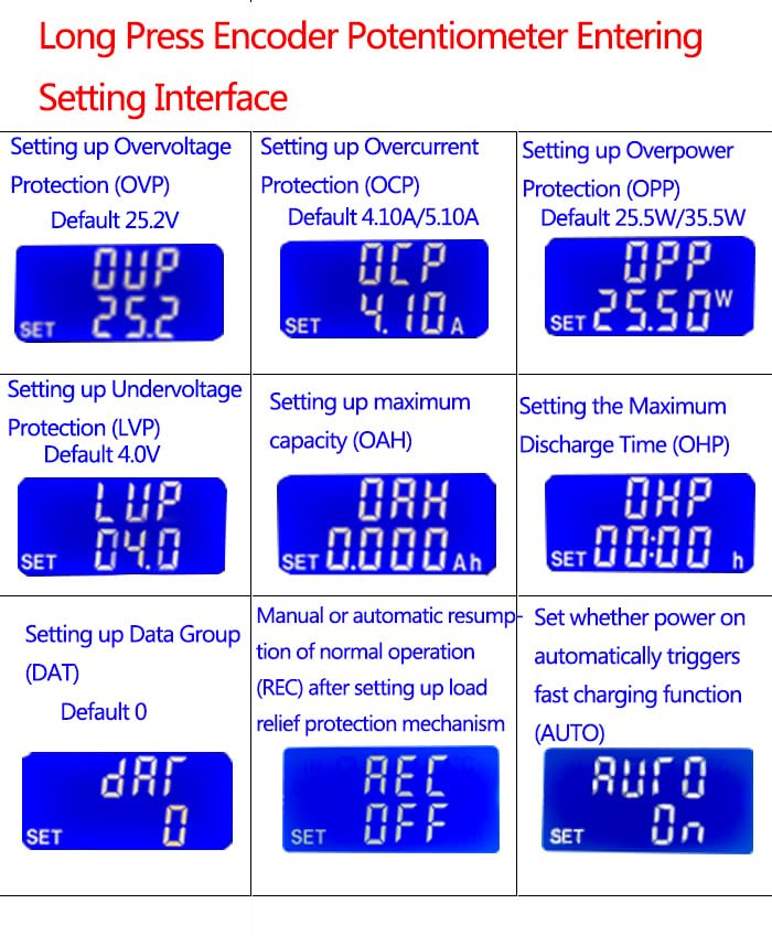
Figure 4.2: Examples of display modes for Electric current, Power, Capacity, and Time.
5. Fast Charge Protocol Triggering
The KZ35 supports mainstream fast charging protocols for testing chargers and power sources.
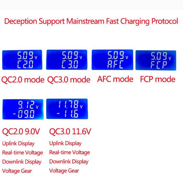
Figure 5.1: Examples of fast charge protocol displays (QC2.0, QC3.0, AFC, FCP).
- Entering Trigger Selection: Short press the "TRG" button to enter the trigger protocol selection interface.
- Selecting Protocol: Rotate the encoder potentiometer to select the desired protocol (QC2.0, QC3.0, AFC, FCP). Short press the encoder potentiometer key to trigger the selected protocol. The LCD will dynamically display "---" during the trigger process.
- Automatic Protocol Detection: Long press the "TRG" button to automatically detect which fast charging protocol the connected charger supports. Once detection is complete, the LCD will display "2.3.A.F" corresponding to "QC2.0/QC3.0/AFC/FCP". If unsupported, it will display "-".
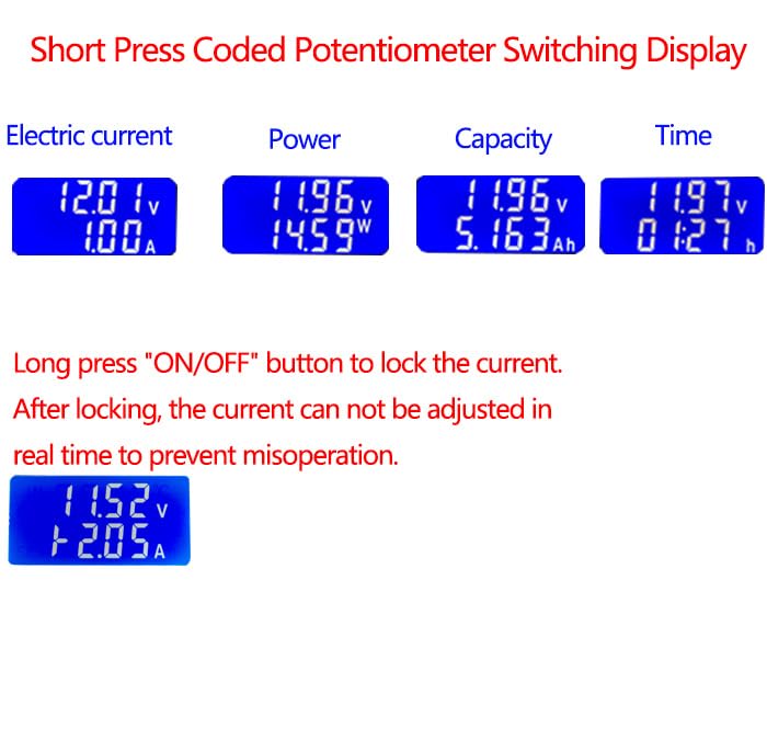
Figure 5.2: Display during automatic fast charge protocol detection.
6. Advanced Settings Interface
Long press the encoder potentiometer to enter the setting interface, allowing configuration of various protection and operational parameters.
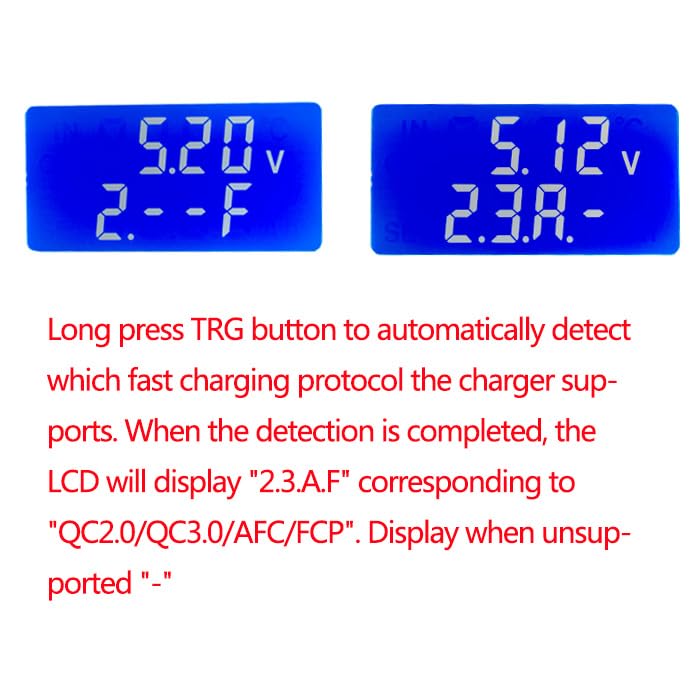
Figure 6.1: Overview of the KZ35 settings interface options.
- Setting Maximum Capacity (OAH): When the OAH function is enabled, the electronic load automatically stops and flashes "OAH" if the discharge capacity exceeds the set maximum. Capacity statistics are cleared upon alarm reset.
- Setting Maximum Discharge Time (OHP): When the OHP function is enabled, the electronic load automatically stops and flashes "OHP" if the running time exceeds the set maximum. Time statistics are cleared upon alarm reset. When OHP is on, the running time is in countdown mode.
- Data Set Features (DAT):
- DAT0: Flashes only the capacity and running time of the previous stage; does not accumulate to the next stage.
- DAT1: Flashes the capacity and running time of the previous stage, and automatically accumulates to the next stage.
- Return to Normal Operation (REC Function):
- REC:ON: The load automatically resumes normal operation after a protection mechanism is triggered and released.
- REC:OFF: The load requires manual intervention to resume normal operation after a protection mechanism is released.
- Automatic Fast Charge Trigger (AUTO Function):
- AUTO:ON: Automatically triggers fast charge upon power-on, suitable for batch testing/aging chargers.
- AUTO:OFF: Does not trigger fast charge upon power-on.
Note: OAH and OHP functions enable unattended power aging testing. When OAH and OHP are not enabled, the electronic load records discharge capacity and time. When enabled, the load stops after reaching the set value.
7. Maintenance
To ensure the longevity and accurate operation of your KZ35 Electronic Load Tester, follow these maintenance guidelines:
- Keep the device clean and free from dust. Use a soft, dry cloth for cleaning.
- Avoid exposing the device to extreme temperatures, humidity, or direct sunlight.
- Do not block the fan vents to ensure proper heat dissipation.
- Store the device in a cool, dry place when not in use.
8. Troubleshooting
If you encounter issues with your KZ35 Electronic Load Tester, refer to the following common problems and solutions:
- Device not powering on: Ensure the power source is connected correctly and providing sufficient voltage (DC4.0-25.0V). Check cable connections.
- Fan not spinning: The fan is temperature-controlled and will only activate when the current reaches approximately 0.22A or when the internal temperature rises. This is normal operation.
- Current cannot be adjusted: Check if the data lock function is enabled (indicated by "|-" on the display). Long press the "ON/OFF" button to disable it.
- "OAH" or "OHP" displayed: This indicates that the set maximum capacity (OAH) or maximum discharge time (OHP) has been reached. The load has stopped automatically. Reset the alarm by clearing the data or adjusting the settings.
- Fast charge protocol not triggering: Ensure the connected charger supports the selected protocol. Some MicroUSB interfaces may not support decoy triggering.
9. Specifications
| Attribute | Value |
|---|---|
| Model | KZ35 |
| Rated Operational Current | 0.03-5.00A (Fan starts at 0.22A) |
| Rated Operational Voltage | DC4.0-25.0V |
| Max Power Dissipation | 35W |
| Supported Fast Charge Protocols | QC2.0 (5V, 9V, 12V, 20V), QC3.0, AFC9V, FCP |
| Protection Features | Reverse Solution Protection, OVP, OCP, OPP, LVP, OAH, OHP |
| Dimensions | Approx. 3.94 x 1.18 x 0.79 inches |
| Weight | Approx. 2.12 ounces |
| Manufacturer | GODIYMODULES |
10. Warranty and Support
This product is manufactured by GODIYMODULES. For specific warranty information and technical support, please refer to the documentation provided at the time of purchase or contact your retailer. Keep your purchase receipt for warranty claims.
