1. Introduction
This manual provides detailed instructions for the safe and efficient operation of your AGAGA NPS-W series miniature switching DC power supply. These power supplies are designed to offer stable and adjustable voltage and current output, making them suitable for various applications including laboratory testing, production line testing, mobile phone and computer maintenance, and battery charging.
The NPS-W series improves upon traditional linear power supplies by offering a compact size, lighter weight, and higher efficiency. The output voltage and current can be precisely controlled using variable resistors, and the high-precision three-window digital display provides real-time readings of voltage, current, and power.
2. Package Contents
Please verify that all items listed below are included in your package. If any items are missing or damaged, please contact customer support.

Figure 2.1: Package Contents Overview
- AGAGA NPS-W Series DC Power Supply Unit (x1)
- AC Power Cord (with three plug options) (x1)
- Output Line (x1)
- Banana Head Output Line (x1)
- Multimeter Pen Line (x1)
- User Manual (x1)
3. Product Overview
3.1 Front Panel Layout
The front panel provides all necessary controls and displays for operating the power supply.

Figure 3.1: Front Panel Controls and Displays
- Voltage Display: Shows the output voltage in Volts (V).
- Current Display: Shows the output current in Amperes (A).
- Power Display: Shows the output power in Watts (W).
- V-COARSE / V-FINE: Knobs for coarse and fine adjustment of the output voltage.
- A-COARSE / A-FINE: Knobs for coarse and fine adjustment of the output current.
- ON/OFF Switch: Main power switch for the unit.
- Negative Contact (-): Output terminal for negative connection.
- Positive Contact (+): Output terminal for positive connection.
- C.V. (Constant Voltage) Indicator: Illuminates when the unit is operating in constant voltage mode.
- C.C. (Constant Current) Indicator: Illuminates when the unit is operating in constant current mode.
3.2 Rear Panel Layout
The rear panel contains the AC power input and cooling components.
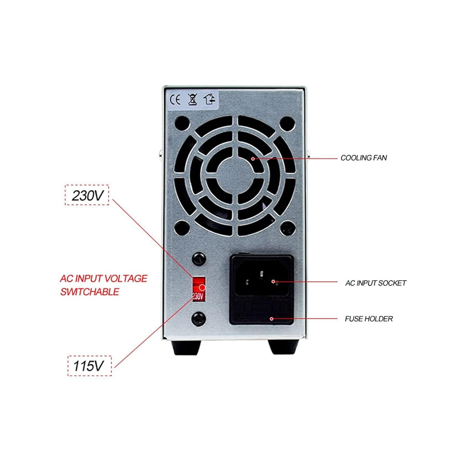
Figure 3.2: Rear Panel Features
- Cooling Fan: Provides active cooling for the internal components.
- AC Input Socket: Connects the power supply to the main AC power source using the provided power cord.
- Fuse Holder: Contains the protective fuse for the unit.
- AC Input Voltage Switch: Allows selection between 115V and 230V AC input voltage. Ensure this is set correctly for your region before connecting to power.
4. Setup Instructions
- Unpacking: Carefully remove the power supply and all accessories from the packaging. Inspect for any signs of damage.
- Placement: Place the power supply on a stable, flat surface with adequate ventilation. Ensure the cooling fan at the rear is not obstructed.
- Voltage Selection: Before connecting the AC power cord, check the AC Input Voltage Switch on the rear panel. Set it to either 115V or 230V according to your local mains voltage. Incorrect voltage selection can damage the unit.
- Power Connection: Connect the provided AC power cord to the AC Input Socket on the rear panel and then plug the other end into a grounded wall outlet.
- Initial Power On: Turn the ON/OFF switch on the front panel to the "ON" position. The digital displays should illuminate.
- Output Connection: Connect your load or circuit to the positive (+) and negative (-) output terminals on the front panel using appropriate cables (e.g., output line, banana head output line, multimeter pen line). Ensure correct polarity.
5. Operating Instructions
5.1 Adjusting Voltage and Current
The power supply operates in either Constant Voltage (CV) or Constant Current (CC) mode, indicated by the respective LEDs on the front panel.
- Setting Voltage (CV Mode):
- Ensure no load is connected or the load is disconnected.
- Turn the A-COARSE and A-FINE knobs fully clockwise to set the current limit to maximum.
- Adjust the V-COARSE and V-FINE knobs to set the desired output voltage. The voltage display will show the set value. The C.V. indicator should be lit.
- Connect your load. The voltage will remain constant at the set value as long as the current drawn by the load does not exceed the set current limit.
- Setting Current (CC Mode):
- Connect a short circuit (e.g., a low-value resistor or a shorting wire) across the output terminals.
- Turn the V-COARSE and V-FINE knobs fully clockwise to set the voltage to maximum.
- Adjust the A-COARSE and A-FINE knobs to set the desired output current. The current display will show the set value. The C.C. indicator should be lit.
- Remove the short circuit and connect your actual load. The current will remain constant at the set value, and the voltage will adjust according to the load's resistance.
- Normal Operation: In typical use, you will set both a voltage and a current limit. The power supply will operate in CV mode until the load attempts to draw more current than the set limit, at which point it will switch to CC mode to protect the load and the power supply.
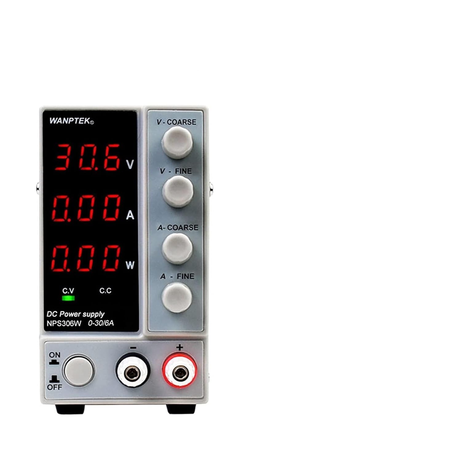
Figure 5.1: Example of Power Supply Display in Constant Voltage Mode
6. Specifications
The AGAGA NPS-W series offers various models with different voltage and current capabilities. The specifications below are general for the series, with specific details for the NPS605W (Four-Digit Display) shown in the image.

Figure 6.1: NPS605W (Four-Digit Display) Key Features
| Parameter | Description |
|---|---|
| Input Voltage | AC 115V/230V ±10% (Switchable) |
| Output Voltage Range | 0-30V (NPS306W, NPS3010W), 0-60V (NPS605W), 0-120V (NPS1203W) |
| Output Current Range | 0-6A (NPS306W), 0-10A (NPS3010W), 0-5A (NPS605W), 0-3A (NPS1203W) |
| Display Accuracy | Three-digit: 0.1V/0.01A; Four-digit: 0.01V/0.001A |
| Display Type | Three-window digital tube display (Voltage, Current, Power) |
| Operating Mode | Constant Voltage (CV), Constant Current (CC) |
| Protection Features | Over temperature protection, Overload protection, Short circuit protection |
| Cooling | Temperature controlled fan cooling |
| Dimensions (Approx.) | 230mm (L) x 70mm (W) x 130mm (H) (Refer to Figure 6.2) |
| Item Weight | Approximately 2000 Grams (4.41 Pounds) |

Figure 6.2: Approximate Dimensions (NPS605W shown)
7. Maintenance
- Cleaning: Disconnect the power supply from the mains before cleaning. Use a soft, dry cloth to wipe the exterior. Do not use abrasive cleaners or solvents.
- Ventilation: Ensure the cooling fan and vents are free from dust and obstructions. Periodically clean the vents with compressed air if necessary.
- Storage: When not in use for extended periods, store the power supply in a cool, dry place, away from direct sunlight and excessive humidity.
- Fuse Replacement: If the unit fails to power on, check the fuse located in the fuse holder on the rear panel. Replace it with a fuse of the same type and rating if blown. Refer to the specifications for the correct fuse type.
8. Troubleshooting
| Problem | Possible Cause | Solution |
|---|---|---|
| Unit does not power on. | No AC power; Blown fuse; Incorrect voltage selection. | Check power cord connection and wall outlet. Replace fuse if blown. Verify AC Input Voltage Switch setting. |
| No output voltage/current. | Output terminals not connected; Voltage/current knobs set to zero; Overload protection activated. | Ensure load is properly connected. Adjust V-COARSE/V-FINE and A-COARSE/A-FINE knobs. Reduce load or check for short circuit. |
| Output voltage/current fluctuates. | Unstable input power; Loose connections; Faulty load. | Ensure stable AC input. Check all cable connections. Test with a different load. |
| Unit overheats. | Obstructed ventilation; Excessive load. | Ensure cooling fan and vents are clear. Reduce load or operate within specified limits. |
| C.C. indicator is always on. | Load resistance is too low, causing the unit to operate in constant current mode. | This is normal if the load draws more current than the set limit. Increase the current limit or reduce the load. |
9. Warranty and Support
AGAGA products are manufactured to high quality standards. For information regarding warranty coverage, technical support, or service, please refer to the warranty card included in your package or contact your point of purchase. Please have your product model number and purchase date ready when contacting support.
For further assistance, you may visit the official AGAGA website or contact their customer service directly. Keep your purchase receipt as proof of purchase for warranty claims.