1. Introduction and Product Overview
The Temank PowMr 3200W Solar Inverter is an integrated unit combining a 3200W pure sine wave inverter, a 60A MPPT solar charge controller, and a 40A AC battery charger. It is designed for off-grid solar systems, converting 24VDC battery power to 110VAC for various household and office loads. This inverter supports both lead-acid (Sealed, AGM, Gel, Flooded) and lithium batteries, offering multiple charging and load output modes to meet diverse application requirements.

Figure 1: Front view of the Temank PowMr 3200W Solar Inverter, showing the LCD display and control buttons.
Key Features:
- Pure Sine Wave Output: Ensures compatibility with sensitive electronics.
- Integrated MPPT Controller: Maximizes solar power harvesting.
- AC Charger: Provides flexible charging from utility or generator.
- LCD & LED Display: Offers real-time system data and operating status.
- Multiple Protection Functions: Includes overload, short-circuit, over-temperature, and battery protection.
- Smart Variable Speed Fan: Optimizes cooling and extends system life.
2. Safety Instructions
Please read and understand all safety instructions before installation and operation. Failure to follow these instructions may result in electric shock, fire, or serious injury.
- Installation must be performed by qualified personnel.
- Ensure all wiring is correctly sized and properly terminated.
- Disconnect all power sources (solar, utility, battery) before performing any maintenance or wiring.
- Do not disassemble the inverter. There are no user-serviceable parts inside.
- Install the inverter in a well-ventilated area, away from flammable materials and moisture.
- Ensure proper grounding of the inverter chassis.
3. Physical Components and Display
The inverter features an intuitive LCD display and control buttons for easy monitoring and configuration.
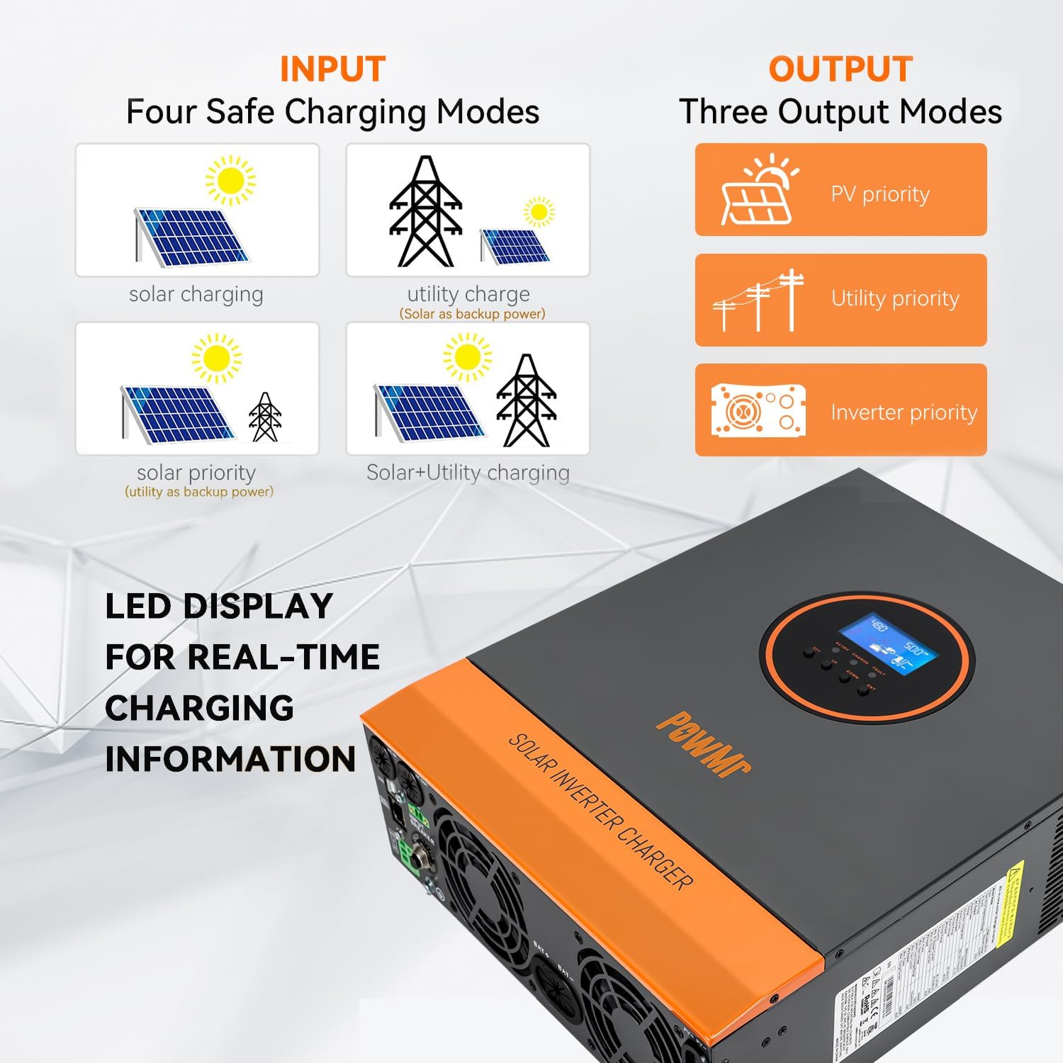
Figure 2: Inverter display showing various input and output modes, along with LED indicators.
LCD Display Overview:
- Upper Section: Displays various values such as battery voltage, AC output voltage, and fault codes.
- Lower Section: Uses icons and arrows to display the current flow in the system's operating modules (e.g., solar, battery, utility, load).
Button Panel:
- SET Button: Used to enter or exit the setting mode.
- UP/DOWN Buttons: Used to switch options, navigate pages, and increase/decrease values.
- ENT Button: Used to enter settings or confirm options.
4. Setup and Installation
Proper installation is crucial for the safe and efficient operation of your solar inverter. Refer to the wiring diagram and follow the steps carefully.
Wiring Guide:

Figure 3: Detailed wiring diagram for connecting the inverter to solar panels, battery, utility/generator, and AC loads.
For a visual guide on wiring, please watch the official video below:
Video 1: Wiring Guide for POW-LVM3.2K-24V Inverter. This video demonstrates the step-by-step process of connecting the battery, AC input, AC output, and PV array to the inverter.
Initial Configuration:
After wiring, proceed with the initial configuration using the LCD display. A detailed setup guide is available in the video below:
Video 2: POW-LVM3.2K-24V Inverter Setup Guide. This video provides a comprehensive walkthrough of all program settings on the inverter's LCD screen.
5. Operating Modes and Settings
The inverter offers various configurable settings to optimize performance based on your specific energy needs and battery type.
AC Output Priority Mode (Setting 01):
- UTI (Utility Priority Mode): Inverter switches to inverter mode only when utility power is unavailable. Load is powered by photovoltaic and battery power.
- SOL (Solar Priority Mode): Inverter prioritizes using solar power for the load. Utility power is used only when solar power is unavailable or battery voltage is below the set value.
- SBU (Inverter Priority Mode): Utility power is used only when battery voltage is below the set value.
Charging Modes (Setting 06):
- SNU (Hybrid Charging Mode): Both solar and utility can charge the battery, prioritizing solar. If solar is insufficient, utility supplements it.
- OSO (Solar Only Charging): Only solar is used to charge the battery; utility is not used.
- CSO (Solar Priority Charging): Prioritizes solar charging. Utility is used only when solar is unavailable.
- CUB (Utility Priority Charging): Solar is used only when utility is unavailable.
Other Key Settings:
- Setting 02 (Output Frequency): 50Hz or 60Hz.
- Setting 03 (AC Input Voltage Range): UPS (90-140V) or APL (170-280V).
- Setting 04 (Battery to Mains): Voltage value at which output switches from battery to utility.
- Setting 05 (Mains to Battery): Voltage value at which output switches from utility to battery.
- Setting 07 (Max. Charging Current): Set according to battery's maximum acceptable charging current.
- Setting 08 (Battery Type): GEL, FLD (Flooded), LI (Lithium), USE (Custom).
- Setting 09 (Boost Charging Voltage): Voltage for boost charging.
- Setting 10 (Boost Charging Max. Time): Maximum duration for boost charging.
- Setting 11 (Float Charging Voltage): Voltage for float charging.
- Setting 12 (Over Discharge Voltage): Voltage at which inverter shuts down due to over-discharge.
- Setting 13 (Over Discharge Delay Time): Delay before inverter shuts down after reaching over-discharge voltage.
- Setting 14 (Battery Under Voltage Alarm Point): Low voltage alarm value.
- Setting 15 (Battery Discharging Limit Voltage): Battery discharge limit voltage.
- Setting 16 (Equalization Charging): Enable/disable equalization charging.
- Setting 17 (Equalize Charging Voltage): Voltage for equalization charging.
- Setting 18 (Equalize Charging Time): Duration for equalization charging.
- Setting 19 (Equalize Charging Delay): Extension time for equalization charging if voltage not reached.
- Setting 20 (Equalize Charging Derating Time): Interval for automatic equalization.
- Setting 21 (Equalize Charging Enable): Immediately start or stop equalization charging.
- Setting 22 (Energy-saving Mode): Enable/disable power-saving mode.
- Setting 23 (Automatic Overload Restart): Enable/disable automatic restart after overload.
- Setting 24 (Automatic Over-temperature Restart): Enable/disable automatic restart after overheating.
- Setting 25 (Buzzer Alarm): Enable/disable the buzzer alarm.
- Setting 26 (Mode Change Alert): Enable/disable the mode switch prompt.
- Setting 27 (Inverter Overload to Bypass): Enable/disable switching to utility bypass output in case of overload.
- Setting 28 (Max. AC Charging Current): Maximum AC charging current.
- Setting 30 (Machine Address Settings): Communication code of the inverter.
- Setting 32 (RS485 Communication): Select SLA for PC/remote monitoring or 485 for BMS communication.
- Setting 33 (BMS Communication Protocols): Select specific BMS communication protocol (e.g., PAC, 866, 882, 89L).
- Setting 35 (Battery Under Voltage Recovery Point): Voltage at which inverter automatically restarts after under-voltage shutdown.
- Setting 36 (Max. PV Charging Current): Maximum photovoltaic charging current.
- Setting 37 (Recharge Recovery Point after Battery is Full): Voltage value at which battery will be recharged after being fully charged.
- Setting 38 (AC Output Voltage Setting): AC output voltage (standby mode only).
- Setting 39 (Charging Current Limiting Method): BMS (limited by BMS limit value) or INV (limited by inverter's derating logic) or SET (limited by current value in setting 07).
- Settings 58-62 (SOC Thresholds): Discharge warning SOC, discharge cut-off SOC, charge cut-off SOC, switch to grid output SOC, and switch to inverter output SOC (appear after selecting lithium battery BMS communication).
6. Troubleshooting
This section provides guidance for common issues. For complex problems, contact technical support.
- No Power: Check battery connections, DC breaker, and AC input.
- No AC Output: Verify inverter is on, check AC output breaker, and ensure no overload.
- Fault Code Displayed: Refer to the inverter's LCD display for specific fault codes and consult the full manual for detailed explanations and solutions.
- Battery Not Charging: Check solar panel connections, PV input voltage, AC input (if applicable), and charging mode settings.
7. Specifications
| Feature | Specification |
|---|---|
| Product Dimensions | 14.88 x 11.02 x 4.06 inches |
| Item Weight | 14.96 pounds |
| Item Model Number | POW-LVM3.2K-24V |
| Brand | Temank |
| Recommended Uses | Boat, Home, Office, Vehicle |
| Power Source | Battery Powered |
| Wattage | 3200 watts |
| Battery Capacity | 200 Amp Hours (Recommended) |
| Max PV Input Power | 1600W |
| Max PV Input Voltage (VOC) | 108V |
| Max PV Output Current | 60A |
| AC Rate Input/Output Voltage | 120Vac ±5% |
| Hybrid Charging Max Charger Current (AC+PV) | 100A |
8. Warranty and Support
For warranty information, technical support, or service inquiries, please contact Temank customer service. Keep your purchase receipt and product model number handy for faster assistance.
Visit the Temank Store on Amazon for additional products and support resources.


