
1. Introduction
This manual provides essential instructions for the installation, operation, and maintenance of your PowMr 5200W Hybrid Solar Inverter, Model SunSmart SP5.2K. Please read this manual thoroughly before installation and operation to ensure proper use and safety. This inverter is designed to convert 48V DC power from batteries or solar panels into 110V/120V AC power for various applications.

Image 1.1: Front view of the PowMr 5200W Hybrid Solar Inverter, showcasing its display and branding.
2. Safety Instructions
Adherence to these safety guidelines is crucial for preventing injury and damage to the equipment. Always consult a qualified electrician for installation.
- Electrical Hazard: This unit operates with high voltages. Do not attempt to open or service the inverter unless you are a qualified professional.
- Proper Grounding: Ensure the inverter is properly grounded according to local electrical codes.
- Ventilation: Install the inverter in a well-ventilated area to prevent overheating. Do not block ventilation openings.
- Battery Safety: Work with batteries carefully. Wear protective eyewear. Batteries can produce explosive gases.
- Water Exposure: Do not expose the inverter to rain, snow, or liquids of any type.
- Children: Keep the inverter out of reach of children.
3. Product Overview
3.1 Key Features
- 5200W DC 48V hybrid solar inverter with pure sine wave output.
- Built-in 100A MPPT solar charge controller.
- Max. PV Power: 6000W, PV Input VOC: 120-500V DC.
- Supports 48V Lead-acid or Lithium batteries, or can operate without a battery.
- Supports up to 6 inverters connected in parallel for increased capacity (up to 10.4kW in split phase with two inverters).
- Communication support: CAN, USB, and RS485.
- Intelligent power saving (ECO mode) and sectional charging/discharging functions.
- Comprehensive protection features: short circuit, over-current, over/under voltage, overload, and backfeed protection.

Image 3.1: Overview of the PowMr 5200W Hybrid Inverter's key features, including parallel support, cooling fans, ECO mode, and charging/discharge functions.
3.2 Product Components and Display
The inverter features a smart LCD screen and various ports for connectivity and operation.

Image 3.2: Detailed view of the Smart LCD Screen, showing indicators for solar power, mains power, PV parameters, battery parameters, load parameters, and real-time data.

Image 3.3: Diagram illustrating the various ports and components of the inverter, including the dustproof cover, overload protector, ON/OFF switch, AC input/output, communication ports (RS485-2, USB), dry contact port, current sharing port, parallel communication port, PV port, cooling fan, battery port, function keys, and LCD screen.
4. Setup and Installation
4.1 General Connection Diagram
The following diagram illustrates a typical connection setup for the PowMr hybrid solar inverter, integrating solar panels, batteries, mains power/generator, and home loads.

Image 4.1: A comprehensive connection diagram showing inputs from solar panels, mains power, and a generator, and outputs to home loads. It also details connections for a 48V battery bank.

Image 4.2: Detailed connection diagram including specifications for AC input (90-140Vac, 63A), PV input (6000W, 500VDC, 22A), AC output (5200W, 120Vac), and battery input (48V, Lead-acid or Lithium).
4.2 Battery Compatibility and Batteryless Mode
The inverter is compatible with various 48V battery types and supports operation without a battery.
- Compatible Battery Types: FLD (Flooded), SLD (Sealed Lead Acid), AGM, GEL, LI (Lithium), and USER-defined settings.
- Lithium Battery Activation: The inverter includes an activation function for dormant lithium-ion batteries, triggered by either mains or photovoltaic power.
- Batteryless Mode: The inverter can power loads directly from the PV array or AC grid without a connected battery.
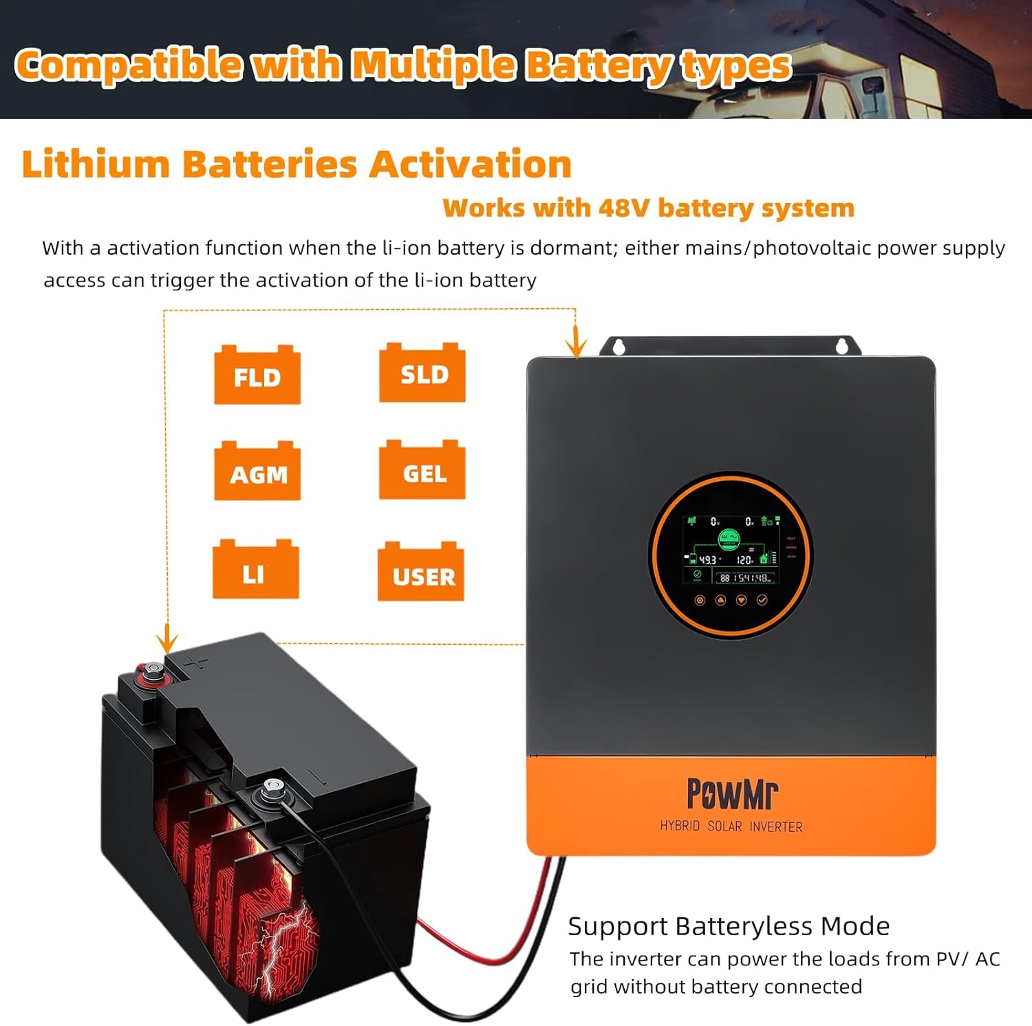
Image 4.3: Visual representation of compatible battery types (FLD, SLD, AGM, GEL, LI, USER) and the inverter's ability to operate in batteryless mode, powering loads directly from PV or AC grid.
4.3 Parallel Operation
The PowMr 5200W inverter supports parallel operation of up to 6 units to increase total power output and support different phase configurations.
- Single Phase: Two inverters can be connected in parallel for single-phase output, up to 10000W.
- Split Phase: Two inverters are required to output 240V/208V in split phase, up to 10400W. Up to 6 inverters can be connected for higher capacity (up to 30000W).
- Three Phase: Three inverters can be connected in parallel for three-phase output, up to 15000W.

Image 4.4: Diagrams illustrating parallel connections for 2 inverters in single phase (up to 10000W), 3 inverters in three phase (up to 15000W), and 6 inverters in split phase (up to 30000W).
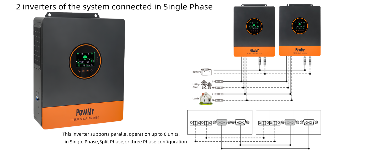
Image 4.5: Connection diagram for two inverters configured for single-phase parallel operation.
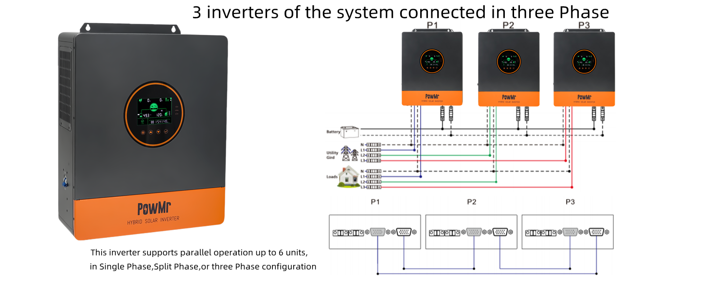
Image 4.6: Connection diagram for three inverters configured for three-phase parallel operation.

Image 4.7: Connection diagram for six inverters configured for split-phase parallel operation.
5. Operating Instructions
5.1 Charging Modes
The inverter supports four distinct charging modes to optimize battery charging based on available power sources.
- Solar First: Priority is given to charging by PV. Mains charging initiates only when PV power is insufficient.
- Mains First: Priority is given to charging by Mains Power. PV power charging initiates only when mains power is unavailable.
- Hybrid Charging: Combines PV and Mains Power charging. Priority is given to MPPT charging. Mains power supplements when PV energy is insufficient and stops when PV energy is sufficient.
- Only Solar: Only PV charging is initiated; no mains charging occurs.

Image 5.1: Diagram illustrating the four charging modes (Solar First, Mains First, Hybrid Charge, Only Solar) and four output modes.

Image 5.2: Detailed visual explanation of the four charging modes and their operational logic.
5.2 Load Output Modes
The inverter offers flexible load output modes to manage power delivery to connected appliances.
- Solar First: PV and battery will power the load. Switches to Mains Power when PV fails.
- Mains First: Switches to inverter power supply only when Mains Power has failed.
- Inverter First: Switches to Mains Power supply only when the battery is under-voltage.
- Hybrid Output: In utility bypass state, when no battery is connected or when the battery is full, the load power is supplied by the PV and the utility together. If the hybrid function is enabled, surplus PV energy can be fed back to the grid if grid connection is enabled.

Image 5.3: Detailed visual explanation of the four load output modes and their operational logic.
5.3 Intelligent Power Saving (ECO Mode)
The ECO mode reduces no-load loss by intelligently managing inverter output.
- When ECO mode is enabled, if the load is below 50W, the inverter output is delayed for 5 minutes and then turned off.
- To resume output, press the hull switch to the "OFF" state, then back to the "ON" state.

Image 5.4: Diagram illustrating the ECO mode functionality, showing how the inverter manages output based on load to reduce power consumption.
5.4 Peak-Valley Electricity Tariff and Sectional Functions
The inverter allows for optimized energy usage based on electricity tariffs.
- Sectional Charging Function (BT1ST Mode): Users can set specific time periods (3 definable periods between 00:00 and 23:59) for mains charging, aligning with lower electricity tariffs.
- Sectional Discharging Function (AC1ST Mode): Users can set specific time periods (3 definable periods between 00:00 and 23:59) for battery discharge, utilizing stored energy during peak tariff hours.

Image 5.5: Graph illustrating peak and valley electricity tariffs and how sectional charging/discharging functions can be configured to optimize energy costs.
6. Maintenance
Regular maintenance ensures the longevity and optimal performance of your inverter.
- Cleaning: Keep the inverter's exterior clean and free from dust. Use a dry cloth. Do not use liquid cleaners.
- Ventilation: Ensure ventilation openings are clear and unobstructed. Periodically check for dust buildup in cooling fans.
- Connections: Periodically inspect all electrical connections for tightness and signs of corrosion.
- Battery Inspection: If using lead-acid batteries, check electrolyte levels and terminal conditions as per battery manufacturer guidelines.
- Environment: Ensure the installation environment remains within specified temperature and humidity ranges.
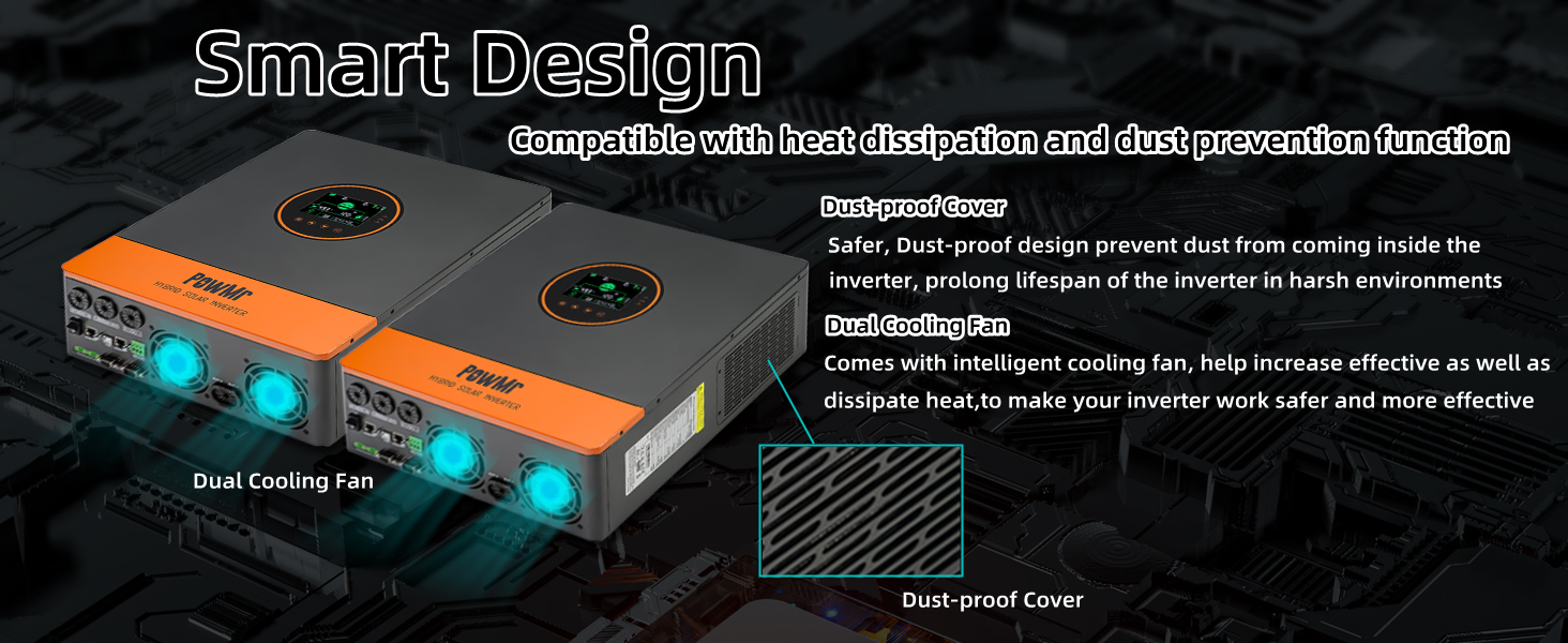
Image 6.1: Illustration of the inverter's smart design features, including dual cooling fans and a dust-proof cover, which contribute to its durability and ease of maintenance.
7. Troubleshooting
This section provides guidance for common issues. For complex problems, contact customer support.
| Problem | Possible Cause | Solution |
|---|---|---|
| Inverter not turning on | No DC input from battery/PV; DC breaker open; faulty wiring. | Check battery connections and voltage; ensure PV input is sufficient; verify DC breaker is closed. |
| No AC output | Overload; short circuit; AC breaker open; ECO mode active. | Reduce load; check for short circuits; close AC breaker; disable ECO mode or cycle power. |
| Battery not charging | PV input too low; charging mode incorrect; battery fault. | Check PV voltage/current; verify charging mode settings; inspect battery health. |
| Overheat warning | Insufficient ventilation; blocked fan; ambient temperature too high. | Ensure proper airflow; clean fan and vents; relocate inverter if necessary. |
8. Specifications
Key technical specifications for the PowMr 5200W Hybrid Solar Inverter.
| Parameter | Value |
|---|---|
| Model Number | SunSmart SP5.2K |
| Rated Power | 5200W |
| Input Voltage (DC) | 48V |
| Output Voltage (AC) | 110V/120V AC (Pure Sine Wave) |
| Max PV Input Power | 6000W |
| PV Input VOC Range | 120-500V DC |
| MPPT Controller Current | 100A |
| Parallel Capability | Up to 6 units |
| Dimensions (L x W x H) | 13.7 x 17.6 x 5.24 inches |
| Weight | 30.8 pounds |
| Communication Ports | CAN, USB, RS485 |
9. Warranty and Support
For warranty information, technical support, or service inquiries, please contact PowMr customer service through their official channels. Retain your purchase receipt for warranty claims.
You can visit the official PowMr store for additional resources and contact information: PowMr Store on Amazon.