
1. Introduction
This manual provides detailed instructions for the safe and effective operation of the Tissting UT801 Series Desktop Type Digital Multimeter. This instrument is designed for precise measurement of AC/DC voltage, AC/DC current, resistance, frequency, capacitance, temperature, triode hFE, diode, and continuity.
The UT801 is a portable benchtop multimeter featuring a 1999-count display, AC and DC power supply capabilities, and a large backlit LCD for clear readings in various lighting conditions. It incorporates full-scale overload protection and is suitable for a wide range of applications in industrial, laboratory, and educational settings.
2. Product Overview and Features

Figure 2.1: Front view of the UT801 Digital Multimeter, highlighting the large display and function selector.
This image displays the front panel of the UT801 multimeter, showing the large digital display, the central rotary function selector, and various input jacks and control buttons. The display is clearly visible, indicating its suitability for benchtop use.

Figure 2.2: Side view of the UT801 Digital Multimeter, showing its compact benchtop design.
This image provides a side perspective of the UT801 multimeter, emphasizing its robust casing and form factor suitable for desktop placement. The design includes a handle for portability.
Key Features:
- Measurement Capabilities: Measures AC/DC voltage, AC/DC current, resistance, frequency, capacitance, temperature, triode hFE, diode, and continuity.
- High Precision: 1999-count display provides high-resolution measurements for various precision needs.
- Dual Power Supply: Operates on both AC and DC power, offering flexibility in different environments.
- Large Backlit LCD: Equipped with a large display and backlight function for clear data readability, even in low-light conditions.
- Overload Protection: Built-in full-range overload safety mechanism ensures instrument durability and user safety.
- Manual Range Selection: Allows users to manually select the measurement range as needed.
- Data Hold Function: Enables freezing of the displayed measurement for easy recording and analysis.
- Ergonomic Design: Designed for ease of use and comfortable handling.
3. Setup
Before operating the multimeter, ensure proper setup for safe and accurate measurements.
3.1 Power Supply Connection

Figure 3.1: Included AC/DC Power Adapter.
This image shows the AC/DC power adapter provided with the multimeter, used for external power supply.

Figure 3.2: Rear panel with power input options.
The rear panel of the multimeter features input options for both battery power (R14 1.5V x 6) and external DC 9V/200mA adapter power. A switch allows selection between BATTERY and ADAPTER power sources. A QR code (C182756136) is also visible.
- AC Power: Connect the provided AC/DC power adapter to the "DC 9V" input jack on the rear panel of the multimeter. Plug the adapter into a standard AC power outlet. Ensure the power switch on the rear is set to "ADAPTER".
- DC (Battery) Power: For portable use, the multimeter can be powered by six R14 (1.5V) batteries. Refer to Section 5.1 for battery installation instructions. Ensure the power switch on the rear is set to "BATTERY".
3.2 Probe Connection
Connect the test leads to the appropriate input jacks on the front panel based on the measurement type. Always ensure secure connections.
- COM Jack: The black (negative) test lead is always connected to the "COM" (Common) jack.
- VΩHz Jack: The red (positive) test lead is connected to the "VΩHz" jack for voltage, resistance, frequency, capacitance, and diode measurements.
- mAµA Jack: The red (positive) test lead is connected to the "mAµA" jack for current measurements up to 200mA.
- 10Amax Jack: The red (positive) test lead is connected to the "10Amax" jack for high current measurements up to 10A.
4. Operating Instructions
This section outlines the general procedures for performing various measurements with the UT801 multimeter.
4.1 Power On/Off
- Press the POWER button () on the front panel to turn the multimeter on or off.
- The LCD backlight can be toggled using the LIGHT button.
4.2 Function Selection
Rotate the central function selector dial to the desired measurement function (e.g., V~ for AC Voltage, V- for DC Voltage, Ω for Resistance, A~ for AC Current, A- for DC Current, etc.).
4.3 Performing Measurements
- Select Function: Turn the rotary switch to the desired measurement function.
- Connect Probes: Insert the test leads into the appropriate input jacks (COM and the relevant measurement jack).
- Connect to Circuit: Connect the test leads to the circuit or component under test.
- Read Display: Observe the measurement value on the LCD.
- Data Hold: Press the HOLD button to freeze the current reading on the display. Press again to release.
Specific Measurement Notes:
- Voltage Measurement: Connect probes in parallel with the circuit. Ensure correct AC/DC voltage selection.
- Current Measurement: Connect probes in series with the circuit. Ensure correct AC/DC current range and appropriate input jack (mAµA or 10Amax).
- Resistance Measurement: Ensure the circuit is de-energized before measuring resistance. Connect probes across the component.
- Diode Test: Connect the red lead to the anode and the black lead to the cathode of the diode. The display will show the forward voltage drop.
- Continuity Test: If the resistance is below a certain threshold, the built-in buzzer will sound, indicating continuity.
- Temperature Measurement: Use a compatible temperature probe (not explicitly mentioned as included, but the function exists).
5. Maintenance
Proper maintenance ensures the longevity and accuracy of your multimeter.
5.1 Battery Installation/Replacement
The UT801 uses six R14 (1.5V) batteries for DC power operation. Refer to Figure 3.2 for the battery compartment location on the rear panel.
- Ensure the multimeter is turned off and disconnected from all power sources and test circuits.
- Locate the battery compartment on the rear of the unit.
- Open the battery compartment cover.
- Insert six R14 (1.5V) batteries, observing correct polarity (+ and -).
- Replace the battery compartment cover securely.
- If the "Low Voltage Display" indicator appears on the LCD, replace the batteries promptly to ensure accurate readings.
5.2 Cleaning
Wipe the case with a damp cloth and mild detergent. Do not use abrasives or solvents. Ensure the multimeter is completely dry before use.
5.3 Storage
When not in use for extended periods, remove the batteries to prevent leakage. Store the multimeter in a cool, dry place away from direct sunlight and extreme temperatures.
6. Troubleshooting
This section provides solutions to common issues you might encounter.
| Problem | Possible Cause | Solution |
|---|---|---|
| No display or dim display | Low batteries; Power adapter not connected or faulty; Multimeter off. | Replace batteries; Check power adapter connection and functionality; Press the POWER button. |
| Incorrect readings | Wrong function selected; Test leads improperly connected; Overload condition; Damaged test leads. | Select correct function; Ensure leads are in correct jacks; Check circuit for overload; Inspect and replace damaged leads. |
| Buzzer not sounding during continuity test | Circuit resistance too high; Multimeter not in continuity mode. | Ensure circuit is closed and resistance is low; Select continuity function. |
| No response from buttons | Multimeter frozen; Internal error. | Turn off and restart the multimeter. If issue persists, contact support. |
7. Specifications
Detailed technical specifications for the Tissting UT801 Digital Multimeter.
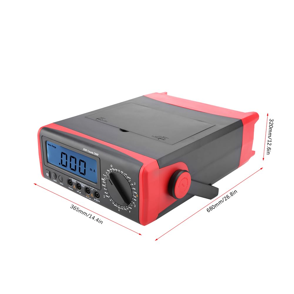
Figure 7.1: Physical dimensions of the UT801 Multimeter.
This image illustrates the physical dimensions of the UT801 multimeter, showing its length (365mm/14.4in), width (680mm/26.8in), and height (320mm/12.6in).
| Parameter | Range | Best Accuracy |
|---|---|---|
| DC Voltage (V) | 200mV/2V/20V/200V/1000V | ±(0.5%+2) |
| AC Voltage (V) | 2V/20V/200V/750V | ±(0.8%+3) |
| DC Current (A) | 200µA/2mA/20mA/200mA/10A | ±(0.8%+2) |
| AC Current (A) | 2mA/20mA/200mA/10A | ±(1.0%+3) |
| Resistance (Ω) | 200Ω/2KΩ/20KΩ/200KΩ/2MΩ/20MΩ | ±(0.8%+3) |
| Capacitance (F) | 20nF/2µF/200µF | ±(4%+3) |
| Frequency (Hz) | 2kHz/200kHz | ±(1.5%+5) |
| Temperature (°C) | -40°C-1000°C | ±(1.2%+3) |
General Characteristics:
- Display Count: 1999
- Manual Range: Yes
- Diode Test: Yes
- Triode Test: Yes
- Continuity Buzzer: Yes
- Low Voltage Display: Yes
- Data Hold: Yes
- LCD Backlight: Yes
- Input Impedance: 10MΩ
- Wrong Use Alarm: Yes
- LCD Size: 108mm*34.5mm
- Product Color: Red and gray
- Product Weight: Approx. 2391g / 84.3oz
- Package Dimensions: 13.78 x 11.81 x 6.69 inches
8. Warranty and Support
For warranty information or technical support, please contact Tissting customer service. Keep your purchase receipt as proof of purchase.
You can visit the official Tissting store on Amazon for more information and support: Tissting Store.
For specific inquiries related to the product, you may reference the model number: Tissting25wufecoy4.