
1. Introduction
This manual provides essential information for the safe and efficient operation of your SRNE SL2410 PWM Solar Charge Controller. The SL2410 is a 12V/24V auto-sensing, 10A Pulse Width Modulation (PWM) solar charge controller designed for various solar power systems, including street lights and monitoring devices. It features an IP67 waterproof rating and an aluminum shell for enhanced durability.
Key Features:
- 12V/24V system voltage auto-detection.
- LED numeric display and waterproof keys for easy operation.
- Advanced 3-stage PWM charging algorithm for battery health.
- Support for multiple battery types: sealed, GEL, flooded lead-acid, ternary-material lithium, and lithium iron phosphate.
- Five load working modes for diverse applications.
- External temperature sensor for precise temperature compensation.
- Power-down saving function for parameter retention.
- Comprehensive protections: overcharge, over-discharge, overload, short-circuit, reverse-connection, and TVS lighting protection.

Figure 1: Front view of the SRNE SL2410 PWM Solar Charge Controller, showing the display, keys, and cable connections.
2. Safety Information
Please read all instructions carefully before installation and operation to prevent damage to the controller, battery, or other components.
- Ensure all wiring is correct and connections are secure before applying power. Incorrect wiring can cause damage.
- Always connect the battery first, then the solar panel, and finally the load. Disconnect in the reverse order.
- Do not attempt to disassemble or repair the controller. Contact qualified personnel for service.
- Install the controller in a well-ventilated area, away from flammable materials.
- Although the controller has an IP67 waterproof rating, avoid submerging it in water or exposing it to extreme conditions beyond its operating temperature range.
- Ensure the system voltage (12V or 24V) matches the controller's auto-detection capability and your battery bank.
- Use appropriate circuit breakers or fuses for the solar panel, battery, and load circuits.
3. Product Overview and Components
The SRNE SL2410 controller features a compact design with clearly labeled connection points and indicators.

Figure 2: Diagram showing the main components and indicators of the SRNE SL2410 controller.
Component Identification:
- Charge Indicator: Displays the status of solar charging.
- Battery Indicator: Shows the battery's charge level and status.
- Load Indicator: Indicates the status of the connected load.
- Key: Used for navigating menus and confirming selections.
- Mode: Used for changing operating modes and settings.
- Connection Leads: Pre-wired cables for solar panel, battery, and load connections.
- Temperature Sensor: External sensor for accurate battery temperature compensation.
4. Setup and Installation
Proper installation is crucial for the controller's performance and longevity.
4.1 Wiring Diagram
Follow the wiring sequence carefully to avoid damage.
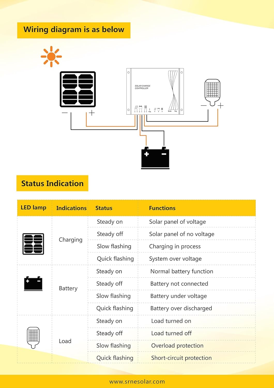
Figure 3: Wiring diagram illustrating connections for the solar panel, battery, and load.
Wiring Steps:
- Connect the Battery: Connect the battery's positive and negative terminals to the corresponding battery connection leads on the controller. Ensure correct polarity. The controller will automatically detect the system voltage (12V or 24V).
- Connect the Solar Panel: Connect the solar panel's positive and negative terminals to the corresponding solar panel connection leads on the controller. Ensure correct polarity.
- Connect the Load: Connect the load's positive and negative terminals to the corresponding load connection leads on the controller. Ensure correct polarity.
Important: Always connect the battery first, then the solar panel, and finally the load. Disconnect in the reverse order: load, then solar panel, then battery.
4.2 Mounting
The controller should be mounted in a location that allows for adequate air circulation. Refer to the dimensions below for installation planning.

Figure 4: Installation dimensions for the SRNE SL2410 controller (dimensions in mm).
Controller Dimensions: 82mm (length) x 58mm (width) x 20mm (height).
5. Operating Instructions
The SRNE SL2410 controller is designed for user-friendly operation with its LED display and waterproof keys.
5.1 LED Status Indication
The controller provides visual feedback through its LED indicators:
| LED Lamp | Indications | Status | Functions |
|---|---|---|---|
| Charging | Steady on | Solar panel of voltage | |
| Steady off | Solar panel of no voltage | ||
| Slow flashing | Charging in process | ||
| Quick flashing | System over voltage | ||
| Battery | Steady on | Normal battery function | |
| Steady off | Battery not connected | ||
| Slow flashing | Battery under voltage | ||
| Quick flashing | Battery over discharged | ||
| Load | Steady on | Load turned on | |
| Steady off | Load turned off | ||
| Slow flashing | Overload protection | ||
| Quick flashing | Short-circuit protection |
5.2 Parameter Settings
The controller allows for various parameter settings using the 'Mode' and 'Key' buttons. The power-down saving function ensures that your settings are retained even after power loss.
- Battery Type Selection: The controller supports sealed, GEL, flooded lead-acid, ternary-material lithium, and lithium iron phosphate batteries. Refer to the controller's display and manual for specific steps to select the correct battery type.
- Load Working Modes: Up to 5 load working modes are available, facilitating application to different types of road lamps and monitoring devices. Consult the detailed product documentation for instructions on configuring these modes.
- Temperature Compensation: The external temperature sensor ensures accurate charging voltage adjustments based on ambient temperature, optimizing battery life.
6. Maintenance
The SRNE SL2410 is designed for low maintenance due to its robust IP67 rating and aluminum casing. However, periodic checks are recommended:
- Inspect Connections: Periodically check all wiring connections for tightness and corrosion. Loose connections can cause voltage drops and overheating.
- Clean the Controller: While waterproof, ensure the controller's surface is clean from dust and debris to maintain optimal heat dissipation. Use a soft, dry cloth.
- Monitor Performance: Observe the LED indicators regularly to ensure the system is operating normally.
7. Troubleshooting
This section provides guidance for common issues. Refer to the LED Status Indication table in Section 5.1 for diagnostic help.
- No Power/Display Off: Check battery connections. Ensure the battery is charged above the controller's minimum operating voltage.
- No Charging (Charging LED off): Verify solar panel connections and ensure there is sufficient sunlight. Check for system over voltage (quick flashing Charging LED).
- Load Not Working (Load LED off): Check load connections. Ensure the battery is not under voltage (slow flashing Battery LED) or over-discharged (quick flashing Battery LED). Check for overload protection (slow flashing Load LED) or short-circuit protection (quick flashing Load LED).
- Battery Not Connected (Battery LED steady off): Recheck battery wiring and ensure secure connections.
- System Over Voltage (Charging LED quick flashing): Ensure the solar panel's open-circuit voltage does not exceed the controller's maximum input voltage.
If issues persist, consult the manufacturer or a qualified technician.
8. Specifications
Technical parameters for the SRNE SL2410 PWM Solar Charge Controller:
| Parameter | Value |
|---|---|
| Model | SL2410 |
| System Voltage | 12V/24V Auto |
| System Current | 10A |
| No-load Loss | 10mA/12V; 13mA/24V |
| Solar Energy Input Voltage | <55V |
| Operating Temperature | -35℃ to +65℃ |
| IP Rating | IP67 |
| Weight | 140g |
| Controller Dimensions (L*W*H) | 82mm * 58mm * 20mm |
| Overvoltage Protection | 17.0V (12V system), 34.0V (24V system) |
| Equalizing Charging Voltage | 14.6V (Sealed), 14.8V (Flooded) |
| Boost Charging Voltage | 14.4V (Sealed), 14.2V (GEL), 14.6V (Flooded) |
| Floating Charging Voltage | 13.8V |
| Overcharge Recovery | 13.2V |
| Under-voltage | 12.0V |
| Over-discharge Voltage | 11.0V |
| Overload and Short-circuit Protection | 1.25 times of rated current: 30s; 1.5 times of rated current: 5s; Over 3 times of rated current: short-circuit protection. |
9. Warranty and Support
For warranty information and technical support, please refer to the documentation provided with your purchase or contact the seller/manufacturer directly. Keep your purchase receipt as proof of purchase.


