
1. Introduction
The Gikfun Advanced SMD/SMT Soldering Practice Kit (Model EK8489) is designed for individuals seeking to enhance their surface-mount device (SMD) and surface-mount technology (SMT) soldering skills. This kit provides a comprehensive training platform with over 300 SMD joints and 313 components, offering a practical experience for mastering precision soldering techniques. It is suitable for vocational students, electronics enthusiasts, and engineers aiming to upgrade their SMT rework certification skills.
This manual provides detailed instructions for assembling and operating the kit, along with essential information regarding components, setup, and troubleshooting.
2. Product Overview
The Gikfun EK8489 kit includes a printed circuit board (PCB) and a variety of SMD components. The PCB features multiple sections designed to practice different types of SMD soldering, including various integrated circuits (ICs), resistors, capacitors, and LEDs. The completed board will demonstrate successful soldering by illuminating LEDs.
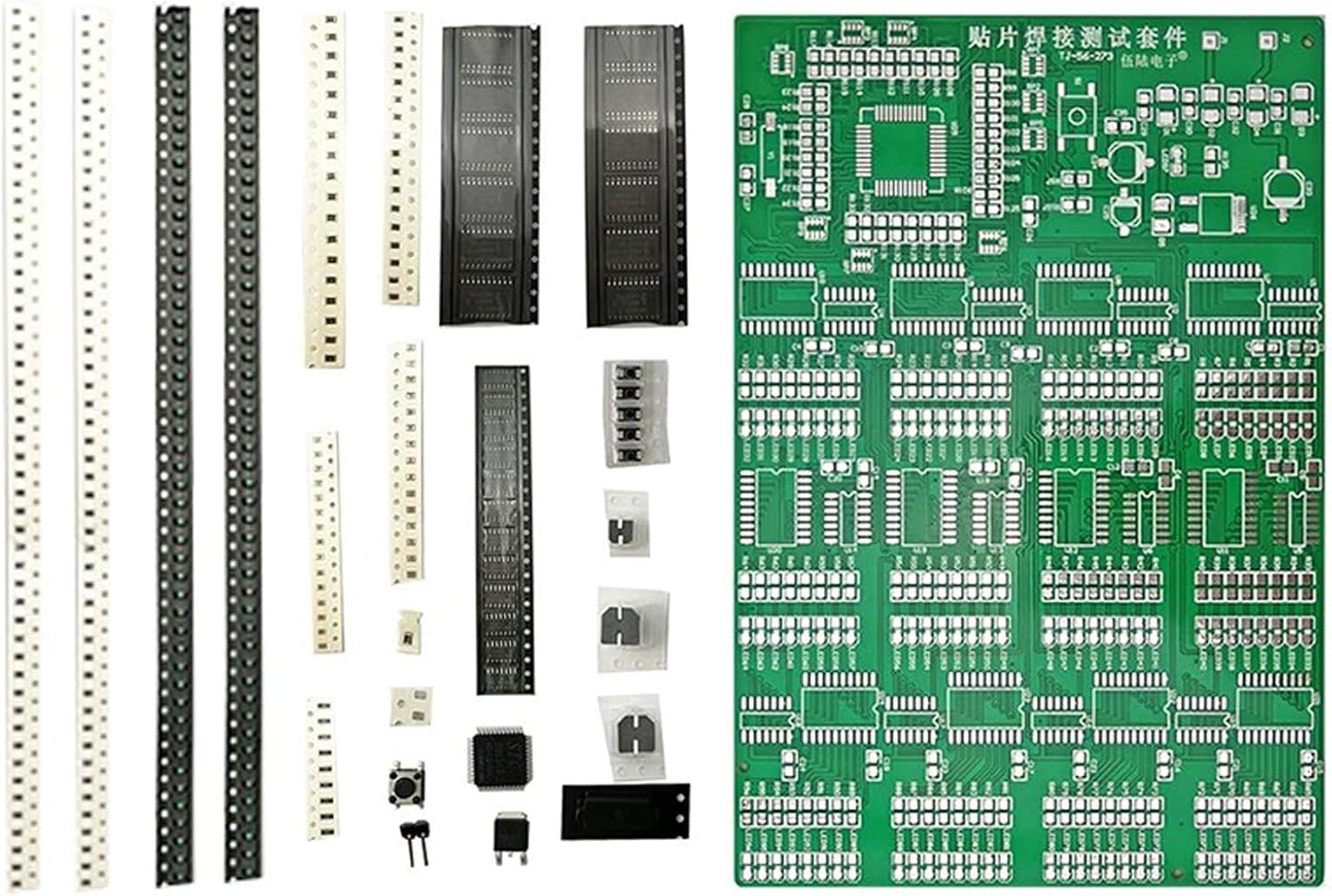
Figure 2.1: Overview of the Gikfun Advanced SMD/SMT Soldering Practice Kit, showing the PCB and various component strips.
3. Components List
The kit contains a main PCB and numerous surface-mount components. It is crucial to identify and sort all components before beginning assembly. Refer to the image below for component identification and placement on the PCB.
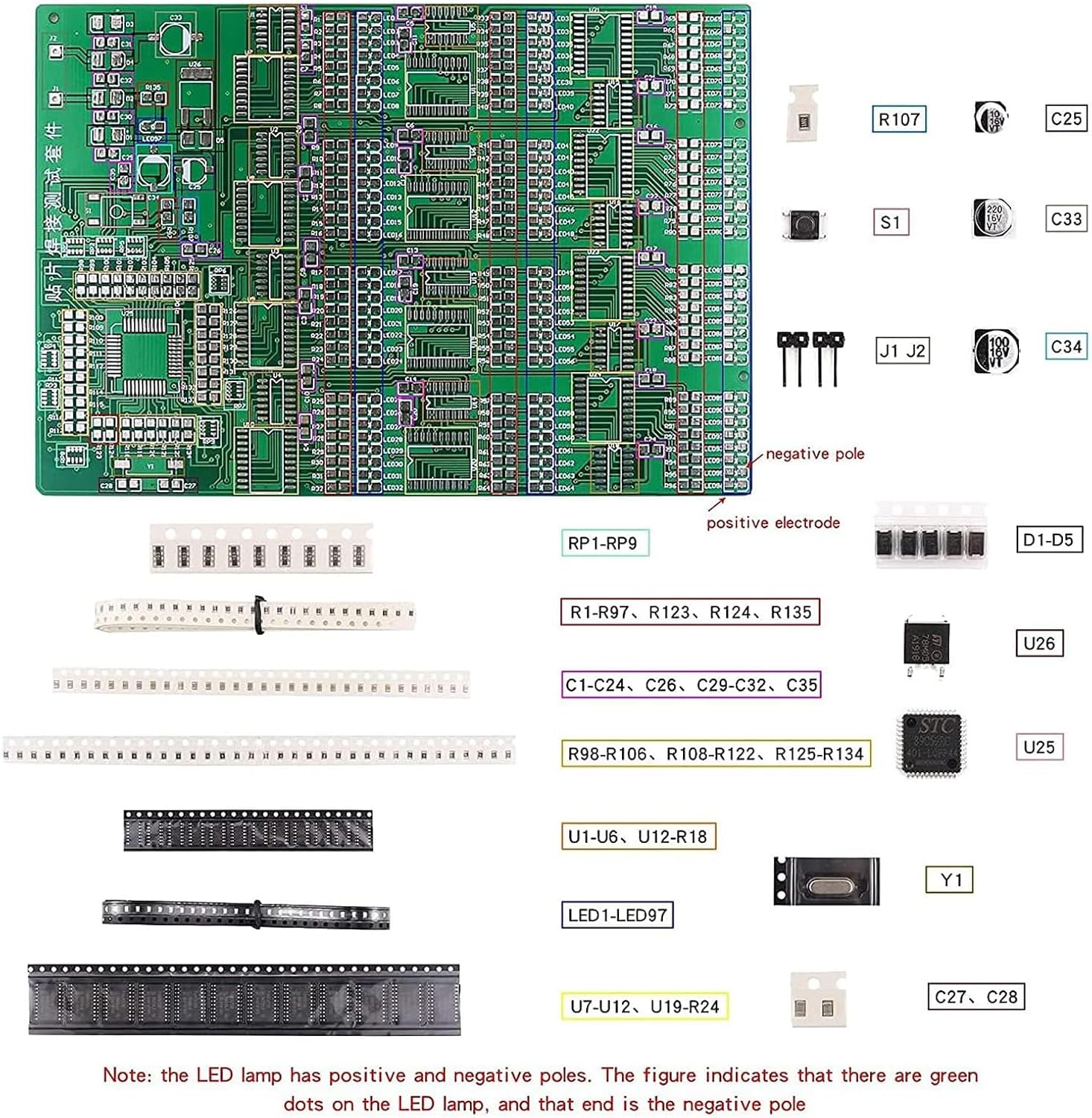
Figure 3.1: Component identification guide, illustrating various SMD components and their designated locations on the practice board. Note the LED polarity: green dots indicate the positive electrode, and the other end is the negative pole.
Key Components:
- Main PCB: The primary circuit board for soldering practice.
- Resistors (R1-R135): Various sizes and values for different soldering challenges.
- Capacitors (C1-C35): Ceramic and electrolytic capacitors.
- Diodes (D1-D5): Small signal diodes.
- Integrated Circuits (U1-U26): Includes various IC packages such as SOIC, SSOP, QFP, and others for advanced practice.
- LEDs (LED1-LED97): Surface-mount LEDs for visual feedback upon successful assembly.
- Crystal Oscillator (Y1): For clock generation.
- Buttons (S1): Tactile switches.
- Connectors (J1, J2): Power input and other connections.
A detailed component list and circuit diagram are available in the online PDF file provided by Gikfun. It is recommended to cross-reference components with this documentation.
4. Setup
Before starting the soldering process, ensure you have the necessary tools and a suitable workspace. This kit requires basic electronic knowledge and hands-on ability. A DC 9V power supply is needed to power the completed board.
Required Tools (Not Included):
- Soldering Iron with fine tip or Hot Air Rework Station
- Solder wire (preferably lead-free)
- Flux (no-clean recommended)
- Tweezers (fine-tip)
- Magnifying glass or microscope
- Multimeter for testing
- DC 9V Power Supply
Preparation:
- Unpack Components: Carefully unpack all components and the PCB.
- Sort Components: Sort components by type and value, referring to the component identification guide (Figure 3.1). This will prevent errors and save time during assembly.
- Prepare Workspace: Set up a clean, well-lit, and well-ventilated workspace. Ensure all necessary tools are within reach.
Video 4.1: Demonstration of component placement and initial soldering steps using a hot air rework station.
5. Operating Instructions (Soldering Process)
This section outlines the general steps for soldering SMD components onto the practice board. It is recommended to start with larger, easier-to-handle components and progress to smaller, more complex ones.
General Soldering Steps (Hot Air Rework Station):
- Apply Solder Paste (Optional): For fine-pitch components, apply a small amount of solder paste to the pads using a stencil or fine-tip dispenser.
- Place Component: Using tweezers, carefully place the SMD component onto its designated pads, ensuring correct orientation (especially for polarized components like ICs and LEDs).
- Apply Heat: Using a hot air rework station, apply heat evenly to the component and its pads until the solder paste reflows and forms solid connections. For components without solder paste, apply a small amount of flux to the pads first.
- Inspect Joint: After cooling, inspect the solder joints for proper formation, ensuring no bridges or cold joints. Use a magnifying glass for detailed inspection.

Figure 5.1: Using a hot air rework station to place and solder an SMD component.
General Soldering Steps (Soldering Iron):
- Tin Pads: Apply a small amount of solder to one pad where the component will be placed.
- Place Component: Hold the component with tweezers and align it with the pads. Heat the tinned pad with the soldering iron and slide the component into place. Remove the iron and allow the solder to cool.
- Solder Remaining Pads: Apply a small amount of flux to the remaining pads. Touch the soldering iron to the pad and component lead simultaneously, then feed a small amount of solder until a good joint is formed. Repeat for all remaining pads.
- Inspect Joint: Inspect all solder joints for proper formation, ensuring no bridges or cold joints.

Figure 5.2: Precision soldering of an SMD component using a fine-tip soldering iron.
Post-Assembly Testing:
Once all components are soldered, connect a DC 9V power supply to the designated input (J1/J2). The LEDs on the board should illuminate, indicating successful assembly and functionality. If some LEDs do not light up, refer to the troubleshooting section.
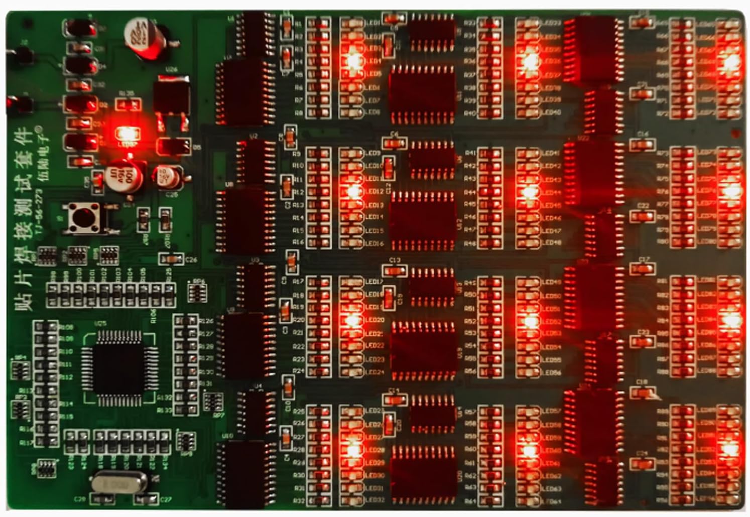
Figure 5.3: The fully assembled practice board with all LEDs successfully illuminated, demonstrating proper soldering.

Figure 5.4: Close-up inspection of the completed and powered practice board.
6. Maintenance
The Gikfun SMD/SMT Soldering Practice Kit is designed for durability and repeated use for practice. Proper maintenance ensures its longevity:
- Cleaning: After soldering, clean any flux residue from the PCB using an appropriate PCB cleaner and a soft brush. This prevents corrosion and ensures clear visibility of solder joints.
- Storage: Store the PCB and any remaining components in a dry, anti-static environment. Keep them away from dust and moisture.
- Handling: Handle the board by its edges to avoid damaging components or solder joints.
7. Troubleshooting
If the assembled board does not function as expected (e.g., LEDs not lighting up), consider the following troubleshooting steps:
| Problem | Possible Cause | Solution |
|---|---|---|
| No LEDs light up. | No power, incorrect power supply, or major short circuit. | Verify 9V DC power supply connection and polarity. Check for visible short circuits. |
| Some LEDs do not light up. | Cold solder joint, solder bridge, incorrect component orientation (LEDs), or faulty component. | Inspect individual LED solder joints and polarity. Check for solder bridges between pins. Re-solder suspicious joints. |
| Board gets hot. | Short circuit. | Immediately disconnect power. Carefully inspect all solder joints for bridges, especially on ICs. Use a multimeter to check for shorts between power and ground. |
| Components fall off. | Insufficient solder or cold joint. | Re-solder the component, ensuring sufficient heat and solder flow. |
For further assistance, refer to the online PDF manual or contact Gikfun customer support.
8. Specifications
| Feature | Detail |
|---|---|
| Brand | Gikfun |
| Model Number | EK8489 |
| Item Weight | 2.96 ounces (84 Grams) |
| Package Dimensions | 7.48 x 4.72 x 0.39 inches |
| Power Source | DC |
| Voltage | 9 Volts (DC) |
| Item Package Quantity | 1 |
| Display Style | Digital (via LEDs) |
| Included Components | Soldering Practice Kit (PCB and various SMD components) |
| Number of SMD Joints | 300+ |
| Number of Components | 313 |
9. Warranty and Support
Gikfun products are designed for quality and performance. This soldering practice kit is intended for educational and skill-building purposes. Due to the nature of DIY assembly, specific warranties on individual components after soldering may vary.
For technical support, component lists, circuit diagrams, or principle descriptions, please refer to the official Gikfun online resources or contact Gikfun customer service directly. You can often find additional support and community forums via the Gikfun Store on Amazon.


