1. Introduction
This manual provides detailed instructions for the installation, operation, and maintenance of your JIESHUO X99-JS11 Motherboard Combo. This combo includes the X99-JS11 motherboard, an Intel Xeon E5-2666 V3 CPU, two 8GB DDR4 2666MHz RAM modules (total 16GB), and a tower CPU cooler. Please read this manual thoroughly before proceeding with installation to ensure proper setup and functionality.
2. Package Contents
Verify that all items listed below are present in your package:
- JIESHUO X99-JS11 Motherboard
- Intel Xeon E5-2666 V3 Processor
- 2 x 8GB DDR4 2666MHz RAM Modules (16GB Total)
- Tower CPU Cooler (including mounting hardware)
- I/O Shield
- SATA Data Cable
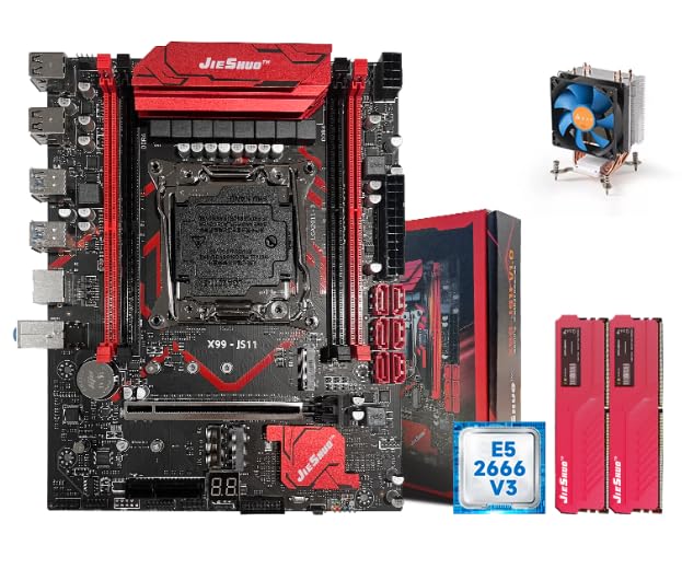
Image 2.1: The complete JIESHUO X99-JS11 motherboard combo, including the motherboard, CPU, RAM modules, and CPU cooler.
3. Product Overview
The JIESHUO X99-JS11 is a high-performance motherboard designed for LGA 2011-3 processors, supporting DDR4 memory. It features robust power delivery and various expansion options suitable for demanding applications.
3.1. Motherboard Layout
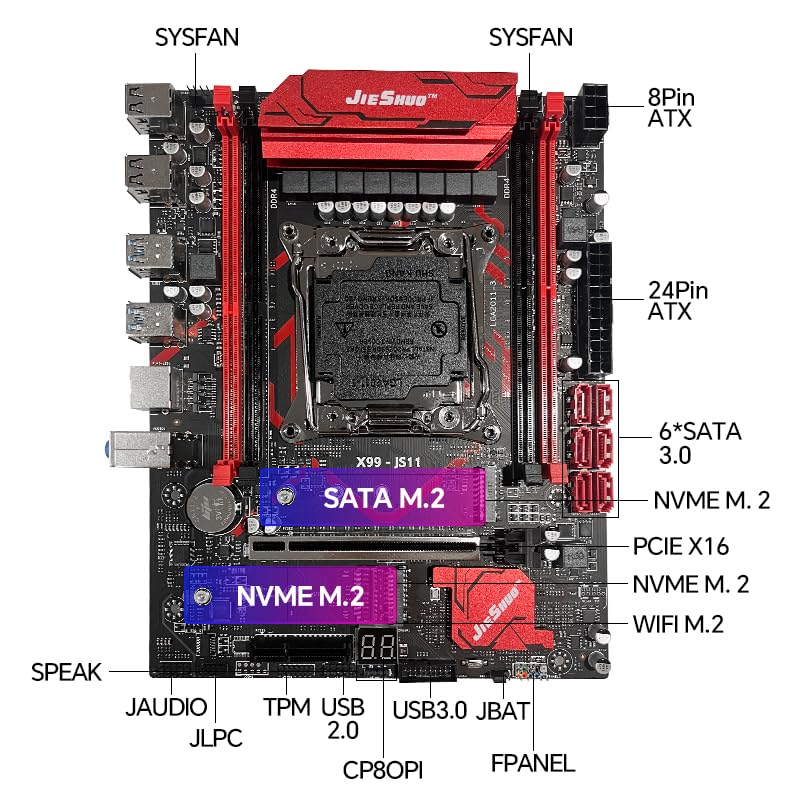
Image 3.1: Detailed diagram of the JIESHUO X99-JS11 motherboard, labeling key components such as CPU socket, RAM slots, PCIe slots, M.2 slots, SATA ports, and power connectors.
- CPU Socket: LGA 2011-3, compatible with Intel Xeon E5 series and Intel Core i7-4000 series processors.
- Memory Slots: 4 x DDR4 slots, supporting up to 64GB RAM in a 4-channel architecture. Supports DDR4 3200/2933/2800/2666/2400/2133MHz.
- Expansion Slots: 1 x PCI Express 16x slot, 1 x PCI Express 4x slot.
- Storage: 2 x NVME M.2 connectors for high-speed SSDs, 4 x SATA 3.0 ports.
- Power Connectors: 1 x 24-pin ATX power connector, 1 x 8-pin ATX power connector.
- Connectivity: Integrated WiFi connector for wireless network card modules.
- Diagnostic Display: Digital status display and buzzer for clear motherboard operating status.
3.2. Rear I/O Panel
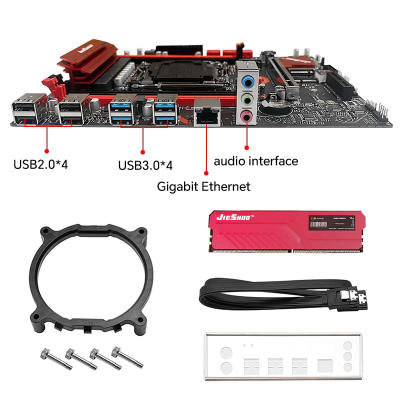
Image 3.2: Close-up view of the JIESHUO X99-JS11 motherboard's rear I/O ports, including USB 2.0, USB 3.0, Gigabit Ethernet, and audio interfaces, along with included accessories like the CPU cooler bracket, SATA cable, and I/O shield.
- 1 x PS/2 port
- 4 x USB 2.0 ports
- 2 x USB 3.0 ports
- 1 x Gigabit RJ45 Port
- 1 x 3-in-1 Audio Port (Line In/Line Out/MIC In)
4. Specifications
| Feature | Specification |
|---|---|
| Brand | JIESHUO |
| Model | X99-JS11 |
| CPU Socket | LGA 2011-3 |
| Compatible Processors | Intel Xeon E5 series, Intel Core i7-4000 series |
| Memory Type | DDR4 |
| Memory Slots | 4 (Quad Channel) |
| Max Memory Capacity | 64 GB |
| Memory Frequency | 2133/2400/2666/2800/2933/3200MHz |
| PCIe Slots | 1 x PCIe x16, 1 x PCIe x4 |
| M.2 Slots | 2 x NVME M.2 |
| SATA Ports | 4 x SATA 3.0 |
| USB Ports (Rear) | 4 x USB 2.0, 2 x USB 3.0 |
| Ethernet | 1 x Gigabit RJ45 |
| Audio | 3-in-1 Audio Port |
| Dimensions | Approx. 24 x 19 cm (9.4 x 7.5 in) |
| Weight | Approx. 700 g |
5. Setup Instructions
Follow these steps carefully to assemble and install your motherboard combo into a computer case.
5.1. Preparation
- Ensure your workspace is clean and well-lit.
- Gather necessary tools: Phillips head screwdriver, anti-static wrist strap (recommended).
- Unpack all components carefully.
5.2. CPU Installation
- Locate the LGA 2011-3 socket on the motherboard.
- Gently push down the CPU retention lever and swing it open.
- Align the triangular mark on the Intel Xeon E5-2666 V3 CPU with the corresponding mark on the socket.
- Carefully place the CPU into the socket without forcing it. It should sit flush.
- Close the retention lever to secure the CPU.
5.3. CPU Cooler Installation
- Apply a thin, even layer of thermal paste to the top of the CPU (if not pre-applied to the cooler).
- Attach the CPU cooler mounting bracket to the motherboard, typically from the rear.
- Position the tower CPU cooler onto the CPU, aligning it with the mounting points.
- Secure the cooler using the provided screws or clips, tightening them evenly to ensure good contact.
- Connect the CPU cooler's fan cable to the CPU_FAN header on the motherboard.
5.4. RAM Installation
- Open the clips on both ends of the DDR4 memory slots.
- Align the notch on each 8GB DDR4 RAM module with the notch in the memory slot.
- Insert the RAM module firmly into the slot until the clips snap into place. Install both 8GB modules into the designated slots for dual-channel operation (refer to motherboard manual for specific slot recommendations, usually alternating slots).
5.5. Motherboard Installation into Case
- Install the I/O shield into the rear opening of your computer case.
- Align the motherboard with the standoffs inside the case.
- Secure the motherboard to the standoffs using screws.
5.6. Connecting Peripherals and Power
- Connect the 24-pin ATX power cable from your power supply to the motherboard.
- Connect the 8-pin ATX 12V power cable to the motherboard.
- Connect SATA data cables to your storage devices (HDDs/SSDs) and the motherboard's SATA 3.0 ports.
- Install any NVME M.2 SSDs into the M.2 slots and secure them with the provided screw.
- Connect front panel headers (Power LED, HDD LED, Power Switch, Reset Switch, USB, Audio) to the corresponding pins on the motherboard. Refer to the motherboard's silkscreen labels for correct orientation.
- Install your graphics card into the PCIe x16 slot and secure it. Connect PCIe power cables from the power supply to the graphics card if required.
- Connect other peripherals such as USB devices, monitor, keyboard, and mouse.
6. Operating Instructions
6.1. First Boot
- After connecting all components and power, press the power button on your computer case.
- Observe the digital status display on the motherboard for diagnostic codes.
- The system should power on and display the BIOS/UEFI splash screen.
6.2. BIOS/UEFI Setup
- During startup, press the designated key (usually DEL or F2) to enter the BIOS/UEFI setup utility.
- Configure boot order, date/time, and other system settings as needed.
- Save changes and exit the BIOS/UEFI. The system will restart.
6.3. Operating System Installation
Install your preferred operating system (e.g., Windows, Linux) from a bootable USB drive or DVD. Follow the on-screen instructions for installation.
6.4. Driver Installation
After OS installation, install necessary drivers for the motherboard chipset, audio, network, and any discrete graphics cards. Drivers are typically available from the manufacturer's website or included on a driver disc (if provided).
7. Maintenance
Regular maintenance helps ensure the longevity and stable operation of your system.
- Dust Removal: Periodically clean dust from the CPU cooler, case fans, and motherboard components using compressed air. Ensure the system is powered off and unplugged before cleaning.
- Cable Management: Ensure internal cables are neatly routed to promote airflow and prevent interference.
- BIOS Updates: Check the manufacturer's website for BIOS/UEFI updates. Only update if necessary and follow instructions carefully.
- Software Updates: Keep your operating system and drivers updated for optimal performance and security.
8. Troubleshooting
This section addresses common issues you might encounter.
8.1. No Power
- Check if the power supply is switched on and properly connected to the wall outlet.
- Ensure the 24-pin and 8-pin ATX power cables are securely connected to the motherboard.
- Verify that the front panel power switch cable is correctly connected to the motherboard header.
8.2. No Display
- Ensure your monitor is powered on and connected to the graphics card (or integrated graphics if applicable).
- Reseat the RAM modules. Try booting with one RAM module at a time.
- Reseat the graphics card and ensure any required PCIe power cables are connected.
- Check the CPU cooler installation; improper installation can prevent booting.
8.3. System Instability / Random Restarts
- Check CPU and GPU temperatures. Overheating can cause instability.
- Ensure all power connections are secure.
- Run memory diagnostic tools to check for faulty RAM.
- Verify that all drivers are correctly installed and up to date.
8.4. Digital Status Display Codes
The motherboard features a digital status display. Refer to the motherboard's specific documentation (if available) for a complete list of POST codes and their meanings. Common codes indicate issues with CPU, RAM, or graphics initialization.
9. Warranty and Support
The JIESHUO X99-JS11 Motherboard Combo comes with a 3-year warranty.
For technical support or warranty claims, please contact:
NJ Infotech - Customer Care
Phone: +91 9906910066
Please have your product model (X99-JS11) and purchase details ready when contacting support.


