1. Introduction
This manual provides essential information for the proper installation, operation, and maintenance of your Mechanivis Fardriver EM180 GTS Brushless DC Motor Controller. This controller is designed for electric bike mid-drive motor applications, offering efficient and stable power management. Please read this manual thoroughly before use to ensure safe and optimal performance.
2. Safety Information
Always observe the following safety precautions to prevent injury or damage to the controller and associated equipment:
- Ensure the power supply is disconnected before performing any installation, wiring, or maintenance.
- Verify all wiring connections are correct and secure to prevent short circuits or improper operation.
- Do not expose the controller to excessive moisture, extreme temperatures, or corrosive environments.
- Avoid disassembling the controller. Refer servicing to qualified personnel.
- Use appropriate personal protective equipment (PPE) during installation and maintenance.
3. Product Features
The Fardriver EM180 GTS controller offers the following key features:
- Cost-effective: Provides high performance at a reasonable cost.
- User-friendly: Features a simple interface for convenient use, development, and debugging.
- Strong stability: Equipped with over-voltage, over-current, and overheating protections to ensure long-term stable operation in complex environments.
- Wide applicability: Suitable for industrial automation, electric vehicles, and other fields.
4. Specifications
Technical specifications for the EM180 GTS controller:
| Available Battery Voltage | 48V-72V |
| Rated DC Current | 160A |
| Boost DC Current | 250A |
| Phase Current | 490A |
| Max. Power | 18000W |
| MOSFETs Detail | 24 FET |
| Matched Motor Rated Power | 3KW-5KW |
| Max. Efficiency | 93% |
| Degree of Waterproof | IP67 |
| Flux Weakening Ratio | 200% |
| Certification | CE, CCC |
| Working Communication | Hall Sensor |
| Net Weight | 1.2 kg (approx. 2.64 lbs) |
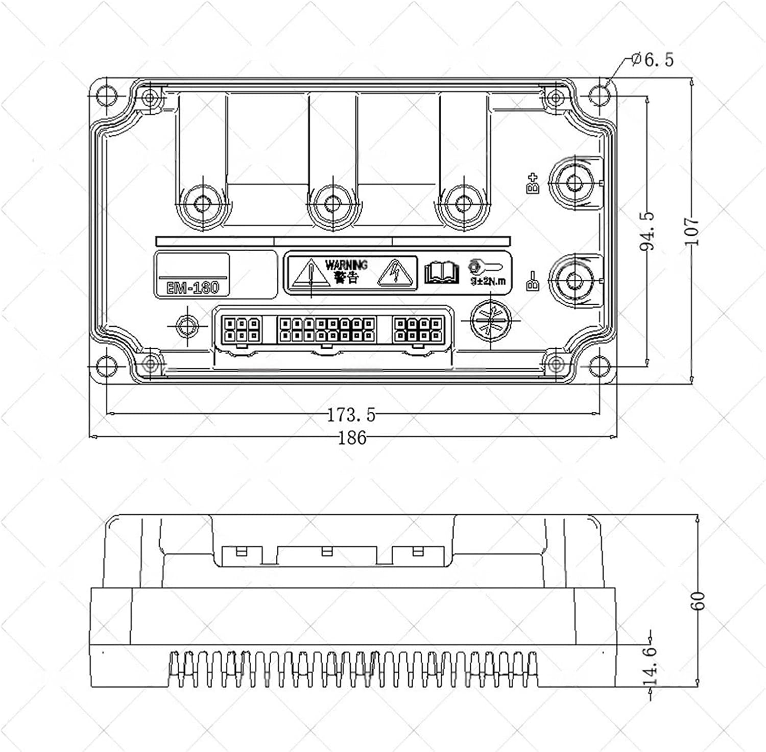
| Dimensions (L x W x H) | 186mm x 107mm x 60mm |
| Programmability | Supported by PC |
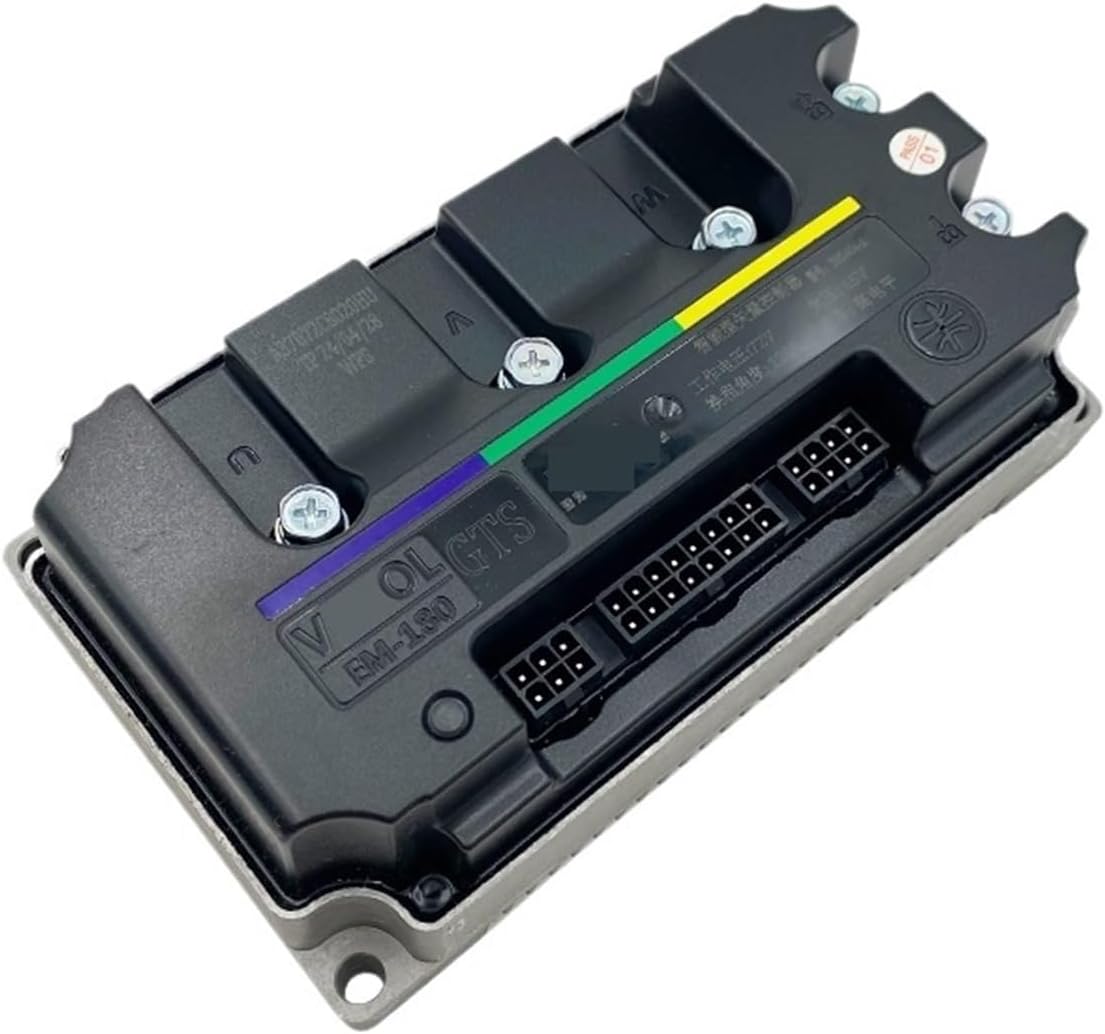
Controller Overview
Dimensional Drawing
5. Setup and Installation
Follow these general steps for installing the EM180 GTS controller. Specific wiring diagrams for your motor and bike model may vary.
- Mounting: Securely mount the controller in a location that allows for adequate airflow for cooling and protects it from physical damage and moisture. Refer to the dimensional drawing (Figure 3) for mounting points.
- Power Connection: Connect the main battery positive and negative terminals to the corresponding power input terminals on the controller. Ensure correct polarity.
- Motor Phase Wires: Connect the three phase wires (U, V, W) from the motor to the corresponding phase output terminals on the controller.
- Hall Sensor Wires: Connect the Hall sensor wires from the motor to the Hall sensor input port on the controller. Ensure the 5V power, ground, and individual Hall signal wires (A, B, C) are correctly matched.
- Throttle Connection: Connect the throttle signal, 5V power, and ground wires to the throttle input port.
- Ignition/Key Switch: Connect the ignition wire to a key switch or power button to control the controller's power state.
- Other Connections: Connect any additional components such as brake levers, speedometer, cruise control, or programming interface as required by your system.
- Initial Check: Before applying full power, double-check all connections for tightness and correctness.
6. Operating Instructions
Once the controller is correctly installed and wired:
- Power On: Turn on the battery power and then activate the ignition switch. The controller should initialize.
- Self-Learning (if applicable): Some controllers have a self-learning function to match motor parameters. Refer to specific programming instructions if available.
- Throttle Control: Gently apply the throttle. The motor should respond smoothly. If the motor spins in the wrong direction, consult the troubleshooting section or programming guide.
- Brake Function: Test the brake levers. Applying the brakes should cut off motor power.
- Monitoring: Observe the motor's behavior and controller's temperature during initial operation.
7. Maintenance
Regular maintenance helps ensure the longevity and reliability of your controller:
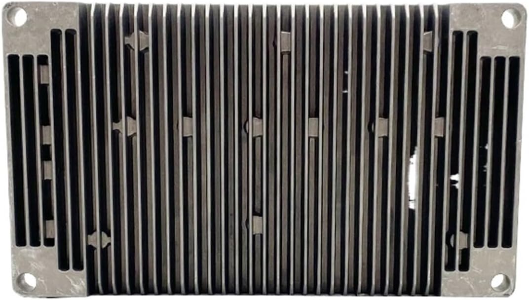
- Cleaning: Periodically clean the exterior of the controller, especially the heat sink fins, to remove dust and debris that can impede cooling. Use a soft, dry cloth.
- Connection Check: Annually inspect all wiring connections for corrosion, looseness, or damage. Tighten any loose connections.
- Environmental Protection: Ensure the controller remains protected from direct water exposure and extreme environmental conditions.
- Firmware Updates: If available, consider updating the controller's firmware via PC programming for improved performance or new features.
8. Troubleshooting
If you encounter issues, refer to the following common problems and solutions:
- No Power:
- Check battery connections and voltage.
- Verify ignition switch is on and functional.
- Inspect main power fuses if present.
- Motor Not Responding to Throttle:
- Check throttle wiring and functionality.
- Ensure Hall sensor wires are correctly connected and not damaged.
- Verify motor phase wires are securely connected.
- Check for active brake signals that might be cutting power.
- Motor Runs in Wrong Direction:
- This typically indicates incorrect Hall sensor or phase wire combinations. Consult the controller's programming software or try different combinations if applicable.
- Overheating:
- Ensure the controller has adequate ventilation.
- Clean heat sink fins if obstructed.
- Reduce load or check for motor issues causing excessive current draw.
9. Related Wiring Reference
This section provides a reference for connecting related components, such as a speedometer. Always refer to the specific documentation for your speedometer model.

10. Warranty and Support
For warranty information and technical support, please contact your retailer or the manufacturer, Mechanivis. Keep your purchase receipt as proof of purchase. Do not attempt to repair the controller yourself, as this may void the warranty.