1. Introduction
This manual provides essential information for the installation, operation, and maintenance of your Mechanivis Fardriver ND72300 Controller Kit. This kit is designed for electric bike mid-drive motor systems, offering precise control and monitoring capabilities. Please read this manual thoroughly before installation and use to ensure proper function and safety.
2. Product Overview
The Fardriver ND72300 Controller Kit includes the main controller unit, an N1S One-LIN display, and a wiring harness. It is designed to manage power delivery to the motor and provide real-time operational data.
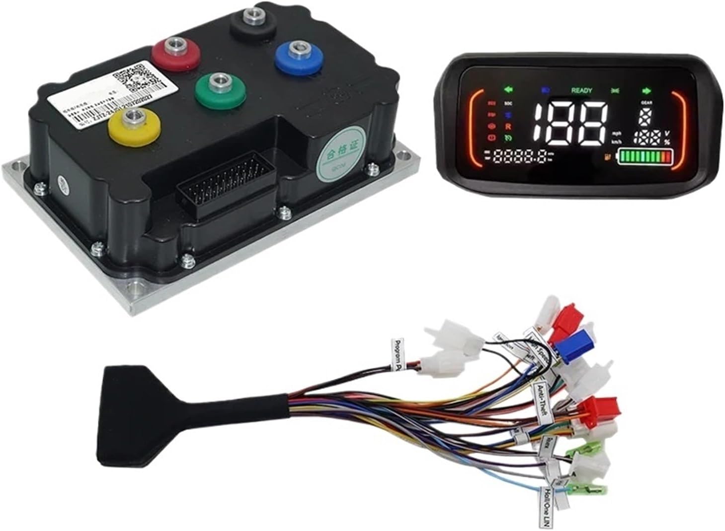
Figure 1: Overview of the Fardriver ND72300 Controller Kit components, including the main controller unit, the N1S One-LIN display, and the associated wiring harness.
3. Setup and Installation
Careful installation is crucial for the optimal performance and safety of your electric bike system. Ensure the battery is disconnected before beginning any installation work.
3.1 Component Identification

Figure 2: Detailed view of the Fardriver ND72300 controller unit with its various ports and the connected wiring harness, showing individual wire labels.
Identify the main controller unit, the N1S display, and the wiring harness. The wiring harness features labeled connectors for various functions.
3.2 Wiring Connections
- Motor Connection: Connect the motor phase wires (typically yellow, green, blue) from your mid-drive motor to the corresponding ports on the controller. Ensure a secure connection.
- Hall Sensor Connection: The controller utilizes Hall sensors for motor commutation. Connect the motor's Hall sensor wires to the designated Hall sensor port on the controller.
- Battery Connection: Connect the main positive and negative battery cables to the controller's power input terminals. Observe correct polarity.
- N1S Display Connection: Connect the N1S One-LIN display cable to the dedicated display port on the wiring harness.
- Throttle Connection: Connect the throttle unit to the throttle input on the wiring harness. The default throttle working voltage is 0V - 5V.
- Other Connections: Connect any additional components such as brake levers, pedal assist sensors (PAS), or lights to their respective labeled connectors on the wiring harness.
3.3 Mounting
Mount the controller securely in a location that is protected from direct water exposure and allows for adequate airflow for cooling. The installing size of the controller is approximately 189mm x 121mm x 65mm. Mount the N1S display on the handlebars for easy visibility.
4. Operating Instructions
Once all connections are secure and the battery is connected, the system is ready for operation.
4.1 Powering On/Off
Turn on the electric bike system using the designated power button, typically located on the N1S display or a separate switch. The display will illuminate, indicating the system is active.
4.2 N1S Display Functions
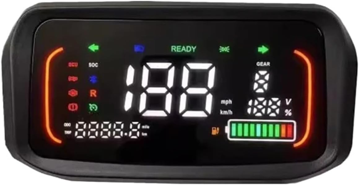
Figure 3: The N1S One-LIN display showing various operational parameters such as speed (mph/km/h), battery level (V and %), gear indicator, and trip distance.
The N1S display provides real-time information about your electric bike's status:
- Speed: Displays current speed in mph or km/h.
- Battery Level: Shows battery voltage and percentage remaining.
- Gear Indicator: Indicates the current assist level or gear.
- Trip/Odometer: Displays trip distance or total odometer reading.
- Error Codes: May display error codes if a system fault is detected. Refer to the troubleshooting section for common codes.
4.3 Throttle and Pedal Assist
Engage the motor using the throttle for direct power or utilize the pedal assist system (if installed) for assistance while pedaling. Adjust assist levels via the display controls if available.
5. Maintenance
Regular maintenance ensures the longevity and reliable operation of your controller kit.
- Keep Clean and Dry: Regularly clean the controller and display with a soft, dry cloth. Avoid exposure to excessive moisture or direct water spray.
- Check Connections: Periodically inspect all wiring connections for tightness and signs of wear or corrosion. Secure any loose connections.
- Cable Management: Ensure all cables are properly routed and secured to prevent snagging or damage during riding.
- Software Updates: If applicable, check the manufacturer's website for any available firmware updates for the controller or display. The controller supports programming via PC and phone.
6. Troubleshooting
This section addresses common issues you might encounter with your Fardriver ND72300 Controller Kit.
6.1 Common Issues and Solutions
- No Power to Display/Motor:
- Check battery charge level.
- Verify all main power connections (battery to controller) are secure and correctly polarized.
- Ensure the power switch is in the 'ON' position.
- Motor Not Responding:
- Check motor phase wire connections.
- Verify Hall sensor connections.
- Inspect throttle connection and functionality.
- Check for any error codes on the N1S display.
- Intermittent Power/Operation:
- Inspect all wiring for loose connections or damaged insulation.
- Ensure the controller is not overheating.
6.2 Safety Protections
The controller is equipped with multiple protections to ensure stable and safe operation:
- Over-voltage protection
- Over-current protection
- Overheating protection
If any of these protections are triggered, the system may temporarily shut down or reduce power. Allow the system to cool down or address the underlying issue before resuming operation.
7. Specifications
Detailed technical specifications for the Fardriver ND72300 Controller Kit:
| Feature | Specification |
|---|---|
| Model | ND72300 |
| Working Communication | Hall Sensor |
| Available Rated Battery Voltage | 48V/60V/72V |
| Battery Voltage (Max) | 88V |
| Available Motor Power | 2000W - 3000W |
| Default Throttle Working Voltage | 0V - 5V |
| Peak DC Current | 100A |
| Peak Phase Current | 300A |
| Mosfets Detail | 18 FET |
| Weight | 2.05 kgs (approximately 4.52 lbs) |
| Installing Size | 189mm x 121mm x 65mm |
| Controller Design | BLDC |
| Case Material | Aluminum |
| Support Programmable | PC & Phone |
| Applicability | Electric bike, scooter, motorcycle, tricycle, kart, ATV |
8. Warranty and Support
For warranty information and technical support, please refer to the documentation provided at the time of purchase or contact Mechanivis customer service directly. Keep your proof of purchase for warranty claims.