1. Safety Information
This manual transfer switch is designed to safely connect a generator to your home's electrical system. Improper installation or use can result in serious injury or death. Always consult a qualified electrician for installation and ensure all local electrical codes are followed.
- Ensure the main utility power is disconnected before working on the electrical system.
- Never operate the generator indoors or in enclosed spaces to prevent carbon monoxide poisoning.
- Do not exceed the maximum wattage or amperage ratings of the transfer switch or individual circuits.
- The double-throw switch design prevents back-feeding power to the utility grid, ensuring safety for utility workers.
2. Product Overview
The VEVOR 30-Amp 10-Circuit Manual Generator Transfer Switch Kit provides a reliable solution for switching between utility power and generator backup during outages. It is compatible with generators up to 7500W.
Key Features:
- 30A, 10-Circuit Capacity: Manages up to 30 amps across 10 circuits, allowing selective power transfer.
- Pre-Wired Design: Simplifies installation with clearly labeled wiring.
- Durable Construction: Features an easy-to-operate double-throw switch and U.S. standard mini circuit breakers for overcurrent protection.
- Mechanical Watt Meter: Provides stable and accurate monitoring of generator load.
- NEMA 3R Weatherproof Enclosure: Suitable for both indoor and outdoor use, protecting internal wiring from harsh conditions.
- Power Input Box Included: Equipped with an L14-30 plug and protective lid for stable power input.
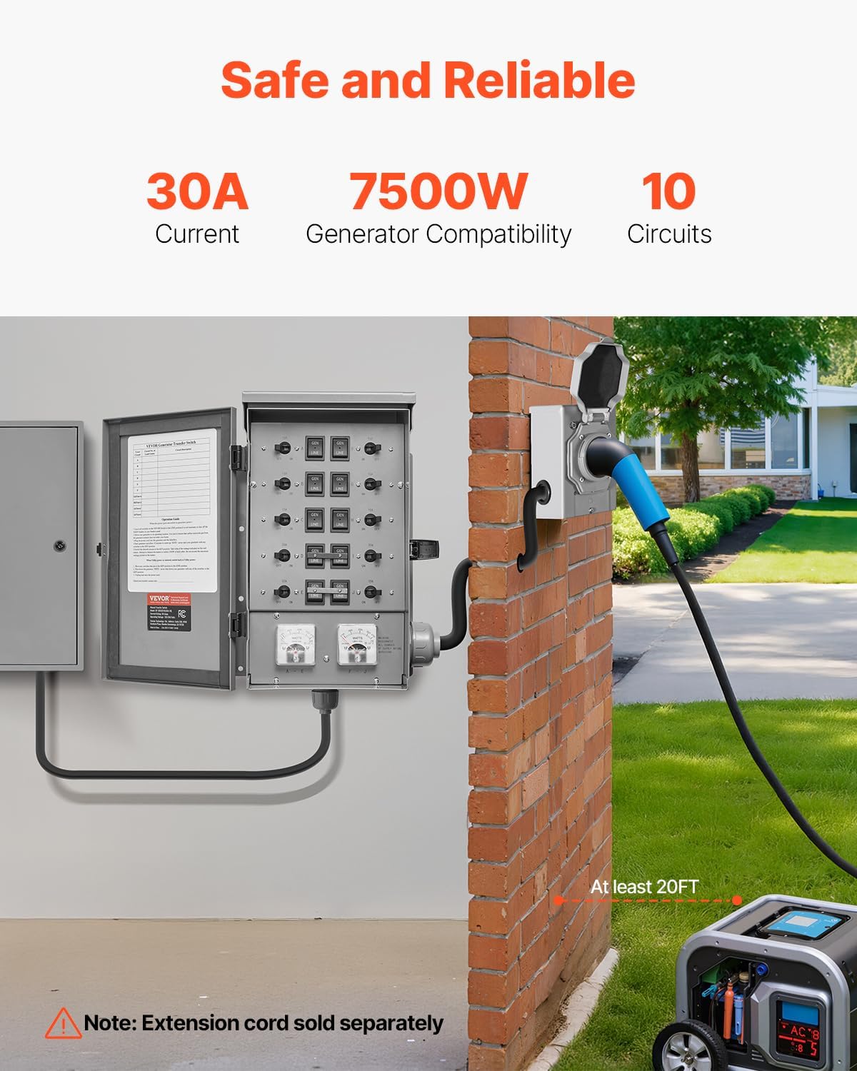
Figure 1: VEVOR 30-Amp 10-Circuit Manual Generator Transfer Switch Kit, highlighting its 30A current, 7500W generator compatibility, and 10 circuits. An external power inlet box is shown connected to a generator.

Figure 2: Detailed view of the transfer switch's internal panel, featuring double-throw switches for generator/line selection and mechanical wattmeters for load monitoring. This illustrates the durable construction and reliable monitoring capabilities.

Figure 3: The NEMA 3R weatherproof enclosure of the VEVOR transfer switch, designed for both indoor and outdoor use, offering protection against rain, snow, intense sunlight, and dust storms.
3. Setup and Installation
The VEVOR transfer switch kit comes pre-wired to simplify installation. However, professional installation by a licensed electrician is highly recommended to ensure compliance with all electrical codes and safety standards.
Components for Installation:
- Manual Transfer Switch (pre-wired)
- NEMA L14-30P Power Inlet Box
- PVC Conduit
- User Manual

Figure 4: The pre-wired design of the transfer switch, featuring clearly labeled wires and robust standard wiring for secure and durable connections, simplifying the setup process.
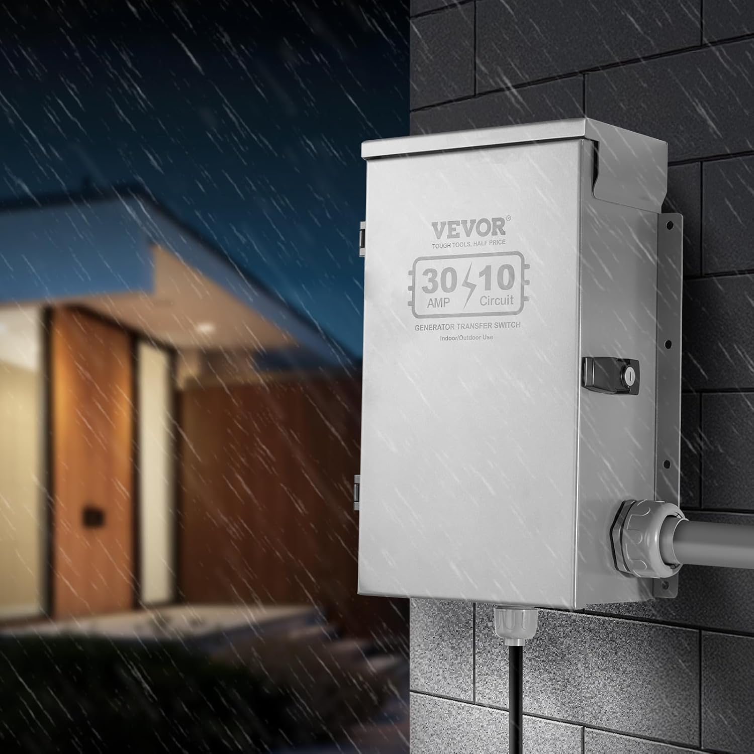
Figure 5: The included power input box, equipped with an L14-30 plug and a protective lid, designed to provide a stable and reliable power input connection from your generator.
Wiring Overview:
The transfer switch connects to your main electrical panel and an external power inlet box. The power inlet box receives power from your generator. The pre-wired nature of the VEVOR switch means the internal connections are largely complete, requiring connection to your home's circuits and the inlet box.
Video 1: This video demonstrates the wiring process for the VEVOR Manual Transfer Switch, including connecting the input wires from the power inlet box, and connecting the output wires to the household distribution box. It also shows how to secure neutral and ground connections and switch between LINE and GEN modes.
Important: The power inlet box should be located a minimum of 10 feet away from any building openings (windows, doors, vents) to prevent generator exhaust from entering your home.
The transfer switch allows you to select specific circuits to be powered by the generator. The internal wiring is clearly labeled (A-J) to correspond with your chosen household circuits.

Figure 6: Internal view of the transfer switch, showing the individual circuit switches (GEN/LINE) and the wattmeters. The labels A-J correspond to the circuits that can be connected.
4. Operating Instructions
Follow these steps to safely transfer power from utility to generator and back:
When Utility Power Goes Out (Switch to Generator Power):
- Leave all switches on the VEVOR Transfer Switch in the LINE position. It is not necessary to shut off the MAIN breaker in your breaker panel.
- Move your generator to its operating location. Ensure the generator exhaust does not enter your home.
- Plug the power cord into the generator and the Inlet Box.
- Start your generator and allow 10 minutes to warm up. NOTE: Never start your generator with any switches in the GEN position.
- Switch the desired circuits to the GEN position. Take note of the wattage indicated on the watt meters. Attempt to balance the meters to within 1000W of each other. Do not exceed the maximum wattage printed on the meters.
When Utility Power is Restored (Switch Back to Utility Power):
- Move any switches that are in the GEN position to the LINE position.
- Shut down the generator. NOTE: Never shut down your generator with any of the switches in the GEN position.
- Unplug and store the power cord.
Refer to the 'Operation Guide' label located on the inside of the transfer switch door for quick reference.
5. Maintenance
Regular maintenance ensures the longevity and safe operation of your transfer switch.
- Periodically inspect all wiring connections for tightness and signs of wear or corrosion.
- Keep the enclosure clean and free from dust, debris, and moisture.
- Ensure the NEMA 3R enclosure seals are intact to maintain weather resistance.
- Test the transfer switch operation periodically (e.g., every 3-6 months) by simulating a power outage with your generator.
6. Troubleshooting
If you encounter issues with your VEVOR Manual Generator Transfer Switch, consider the following:
- No Power to Circuits:
- Check if the generator is running and producing power.
- Ensure the power cord is securely connected to both the generator and the inlet box.
- Verify that the circuit selector switches on the transfer panel are in the 'GEN' position.
- Check the mini circuit breakers on the transfer switch for any tripped breakers.
- Watt Meters Not Registering:
- Confirm that circuits are actively drawing power from the generator.
- Ensure the generator is providing sufficient voltage.
- Unusual Noises or Smells: Immediately shut down the generator and disconnect all power. Contact a qualified electrician for inspection.
7. Specifications
| Feature | Specification |
|---|---|
| Item Model Number | SP-ZH352510(30A-10) |
| Current | 30A |
| Voltage | AC 120/240V |
| Number of Circuits | 10 (2 x 2-Pole + 6 x Single-Pole) |
| Generator Compatibility | 7500W |
| Enclosure Material | Cold-Rolled Steel |
| Net Weight | 19.64 lbs / 8.91 kg |
| Product Dimensions | 14.65 x 9.76 x 4.72 inches (372 x 248 x 120 mm) |

Figure 7: Visual representation of the product dimensions and a summary of key specifications for the VEVOR transfer switch kit.
8. Warranty and Support
VEVOR products are designed for durability and performance. For technical support or warranty information, please refer to the E-Warranty Certificate included with your product or visit the official VEVOR website.
Contact Information:
- Technical Support and E-Warranty Certificate: www.vevor.com/support


