Product Overview
The 5MNG0Y8 XMYC-1 is a single-axis solar tracking controller designed to maximize the energy output of solar panels by automatically adjusting their position to follow the sun's movement. This kit includes the main controller unit, light sensor, wind speed sensor, and proximity limit switches for precise and safe operation. It operates on a 12-24V DC power supply and is suitable for various solar panel tracking applications.

Image 1: The XMYC-1 Single Axis Solar Tracker Controller unit. This image displays the main control box with an LCD screen, control buttons (SET, W-↑, W, E, E+↓, QUIT), and cable glands at the bottom for wiring connections. The label indicates "Single axis sun tracking controller" and "DC IN: 10-28V, I MAX: <15A".
Safety Information
- Ensure all power is disconnected before installation or maintenance.
- Follow all local electrical codes and regulations.
- Only qualified personnel should perform installation and wiring.
- Do not exceed the specified input voltage (10-28V DC) or maximum current (15A).
- Protect the controller from direct exposure to water or extreme weather conditions unless properly sealed.
Package Contents
Verify that all components are present and undamaged upon unpacking.
- XMYC-1 Single Axis Solar Tracker Controller (Main Unit)
- Light Sensor
- Wind Speed Sensor
- Proximity Limit Switches (2 units)
- Remote Control
- Mounting Hardware (screws, etc. - may vary)

Image 2: All components included in the XMYC-1 Single Axis Solar Tracker Kit. This image shows the main controller, a light sensor with a long cable, two blue proximity limit switches with cables, a wind speed sensor (anemometer), and a white remote control.
Product Features
- Automatic single-axis solar tracking.
- Integrated light sensor for precise sun tracking.
- Wind speed sensor for automatic protection in high winds.
- Proximity limit switches for defining movement boundaries.
- Manual control via remote or onboard buttons.
- LCD display for status monitoring.
- Wide operating voltage range: 12-24V DC.
Specifications
| Feature | Specification |
|---|---|
| Model | XMYC-1 |
| Input Voltage | DC 10-28V |
| Max Current | <15A |
| Tracking Type | Single Axis |
| Sensors Included | Light Sensor, Wind Speed Sensor, Proximity Limit Switches |
| Control Method | Automatic (Light-based), Manual (Buttons/Remote), Wind Protection |
| Dimensions (Controller) | Approx. 1.18 x 0.79 x 0.39 inches (Package dimensions, actual unit may vary) |
| Weight | Approx. 1.76 ounces (Item weight, actual unit may vary) |
Installation Guide
1. Mounting the Controller
Mount the XMYC-1 controller in a secure, weather-protected location, close to the solar panel array and power source. Ensure easy access for wiring and operation. Use appropriate screws for mounting.
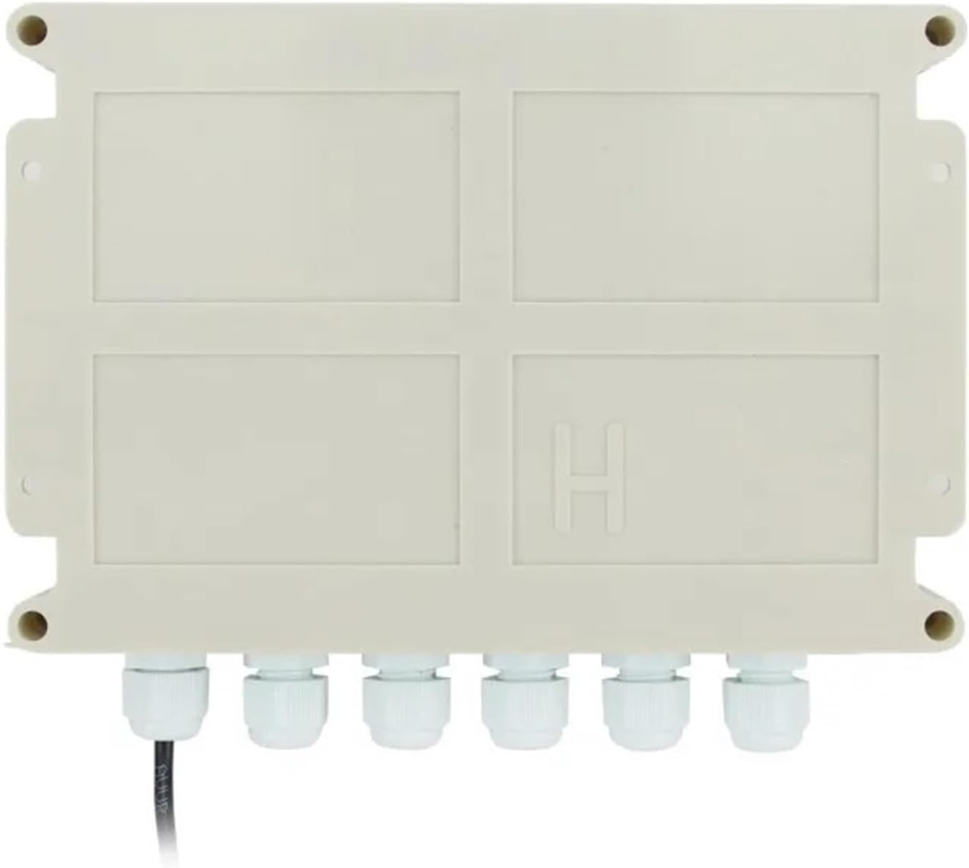
Image 3: Bottom view of the XMYC-1 controller, showing the six cable glands for secure and weather-resistant wiring connections. This design helps protect internal components from environmental elements.
2. Sensor Placement
- Light Sensor: Mount the light sensor in a position where it has an unobstructed view of the sky and can accurately detect the sun's position relative to the solar panel. It should be mounted on the solar panel frame or a nearby structure, ensuring it moves with the panel for accurate tracking.
- Wind Speed Sensor: Install the wind speed sensor in an elevated position, free from obstructions, to accurately measure wind conditions. This sensor is crucial for activating wind protection mode.
- Proximity Limit Switches: Install the two proximity limit switches at the extreme ends of the solar panel's intended movement range. These switches will prevent the panel from over-rotating and causing damage. Ensure they are securely mounted and aligned to be triggered by a moving part of the solar array at the desired limits.
3. Wiring Diagram (Conceptual)
Note: A detailed wiring diagram is typically provided with the product packaging. The following is a conceptual guide. Always refer to the specific diagram included with your unit.
- Power Input: Connect the DC 10-28V power supply to the designated power input terminals on the controller. Observe correct polarity (+/-).
- Motor Output: Connect the solar panel's tracking motor to the motor output terminals. The controller will reverse polarity to control direction.
- Light Sensor: Connect the light sensor cable to its dedicated input port.
- Wind Speed Sensor: Connect the wind speed sensor cable to its dedicated input port.
- Limit Switches: Connect the two proximity limit switches to their respective input terminals (e.g., West Limit, East Limit).
Ensure all connections are secure and properly insulated. Use the cable glands on the controller for weather protection.
Operation Instructions
1. Initial Power-Up
Once all wiring is complete and checked, apply power to the controller. The LCD display should illuminate, showing the current status or initial setup prompts.
2. Setting Limits
Use the manual control buttons (W-↑, E+↓) or the remote control to move the solar panel to its extreme West and East positions. The controller should automatically detect and register these limits via the proximity switches. Consult the specific product manual for detailed calibration steps if required.
3. Automatic Tracking Mode
After setting limits, the controller should enter automatic tracking mode. It will use the light sensor to continuously adjust the solar panel's angle to face the sun, maximizing energy capture.
4. Wind Protection Mode
If the wind speed sensor detects wind speeds exceeding a pre-set threshold, the controller will automatically move the solar panel to a safe, horizontal, or stowed position to prevent damage. Once wind speeds subside, it will resume normal tracking.
5. Manual Control
The remote control and onboard buttons (W-↑, W, E, E+↓) allow for manual adjustment of the solar panel's position. This can be useful for maintenance, cleaning, or specific operational needs. The "QUIT" button may be used to exit certain modes or stop movement.
Maintenance
- Regular Inspection: Periodically check all wiring connections for corrosion or looseness.
- Sensor Cleaning: Keep the light sensor and wind speed sensor clean and free from dust, dirt, or obstructions to ensure accurate readings.
- Limit Switch Check: Verify that the proximity limit switches are functioning correctly and are not obstructed.
- Physical Condition: Inspect the controller housing and cable glands for any signs of damage or water ingress.
Troubleshooting
- Panel Not Moving:
- Check power supply to the controller.
- Verify motor connections and functionality.
- Ensure limit switches are not stuck in a triggered position.
- Check light sensor for obstructions or damage.
- Inaccurate Tracking:
- Clean the light sensor.
- Ensure the light sensor is correctly positioned and moves with the panel.
- Panel Over-rotating:
- Check the wiring and functionality of the proximity limit switches.
- Ensure limit switches are correctly installed and triggered at the desired endpoints.
- Wind Protection Not Activating/Deactivating:
- Check the wind speed sensor for obstructions or damage.
- Verify wind sensor wiring.
Warranty and Support
This product comes with a standard manufacturer's warranty. Please refer to the warranty card included in your package or contact the seller for specific details regarding warranty coverage and support. For technical assistance, please reach out to the manufacturer or your point of purchase.


