
1. Product Overview
The GODIYMODULES 0.36 inch 6 Bit LED Digital Display Module is designed for industrial applications, specifically for use with RS485 ModBus RTU protocol. It can be integrated with PLCs and operates on DC 5V, 12V, or 24V power supplies. This module is capable of displaying numbers, ASCII characters, letters, floating-point numbers, and negative numbers. Its brightness is adjustable, and it supports an electronic label function, allowing for initial display content to be set upon power-on.

Figure 1: Front view of the GODIYMODULES 0.36 inch 6 Bit LED Digital Display Module.
2. Technical Specifications
| Feature | Specification |
|---|---|
| Working Voltage | DC 5V ~ 28V |
| Working Current | 4.3mA ~ 42mA (brightness dependent) |
| Protocol | MODBUS RTU |
| ModBus Commands | 03 (read), 06 or 16 (write) |
| Device Address | 1 ~ 247 (default: 1) |
| Digital Tube Color | Red |
| Digital Tube Digits | 6 digits, 0.36 inches |
| Supported Baud Rates | 1200, 2400, 4800, 9600 (default), 19200, 38400, 57600, 115200 |
| Parity | No parity, Even parity, Odd parity |
| Display Capabilities | Numbers, ASCII characters, letters, floating-point numbers, negative numbers |
| Additional Functions | Adjustable brightness, electronic label function (set initial display content) |
3. Setup and Wiring
This section details the necessary steps for connecting and configuring your LED Digital Display Module.
3.1 Wiring Diagram
The module connects to a power source and an RS485 bus. Ensure correct polarity and voltage to prevent damage.
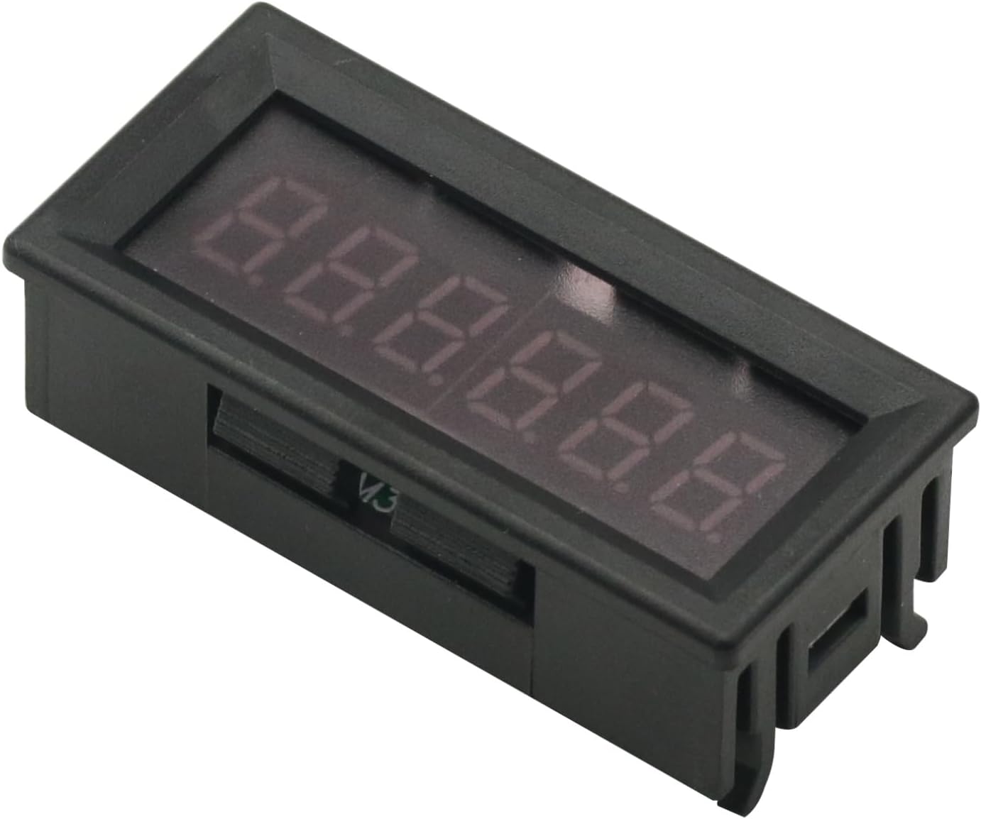
Figure 2: Wiring diagram illustrating the connection of the display module to a PC (via USB to RS485 converter), PLC, and other display modules on an RS485 bus. Power input (VIN, GND) and RS485 data lines (A+, B-) are clearly marked.
Power Connection: Connect DC 5-28V to the VIN and GND terminals. The module supports a wide range of DC input voltages.
RS485 Connection: Connect the A+ and B- terminals to your RS485 bus. Ensure proper A/B line connections for communication.
3.2 Hardware Reset
To perform a hardware reset, short the RES jumper on the board for 5 seconds, then power on the module again. This can resolve certain communication or display issues.
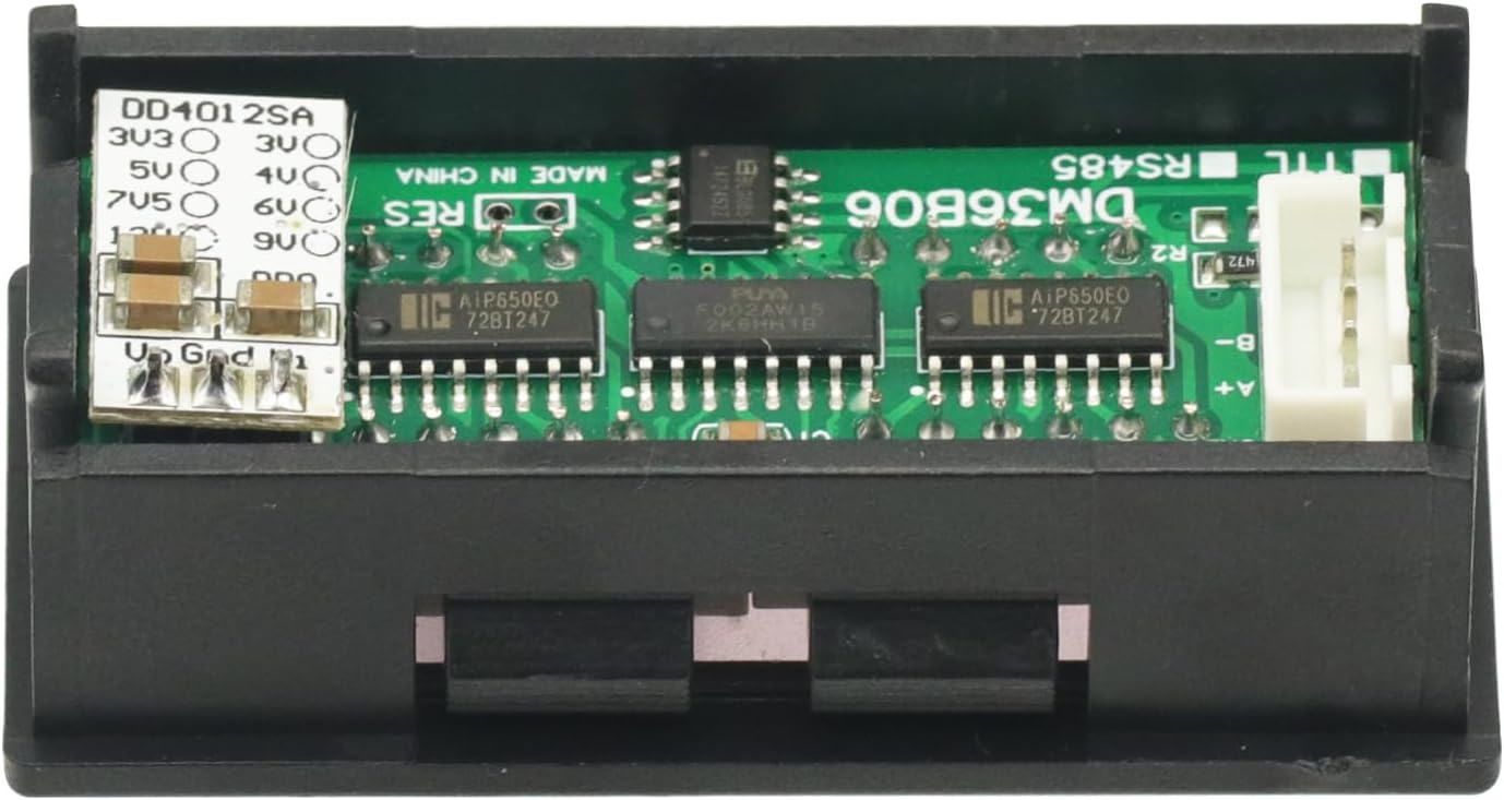
Figure 3: Detailed view of the module's circuit board, indicating the location of the RES jumper for hardware reset and the VIN, GND, A+, B- terminals for power and RS485 connections.
4. Operation and ModBus RTU Communication
The module operates using the ModBus RTU protocol. Communication parameters such as device address, baud rate, and parity can be configured.
4.1 ModBus RTU Commands
- 03 Read Command: Used to read data from the module, such as current display content or configuration settings.
- 06 or 16 Write Command: Used to write data to the module, such as setting new display content, adjusting brightness, or configuring parameters.
4.2 Device Addressing
Each module on the RS485 bus requires a unique device address, ranging from 1 to 247. The default address is 1. For systems with more than 32 modules, an RS485 repeater is recommended to maintain signal integrity.
4.3 Displaying Characters
The module can display a range of ASCII characters. Control characters (00H to 1FH) cannot be displayed. The space character is represented by 20H. Visible ASCII characters range from 21H to 7EH.

Figure 4: ASCII character mapping for the display module, illustrating which characters can be rendered and their corresponding hexadecimal values.
The module supports displaying numbers, English characters, and special symbols as shown in the character map. Ensure the data sent via ModBus RTU corresponds to the supported character set.
5. Maintenance
The GODIYMODULES LED Digital Display Module is designed for low maintenance. Follow these guidelines to ensure optimal performance and longevity:
- Cleaning: Gently wipe the display surface with a soft, dry cloth. Avoid using abrasive cleaners or solvents that could damage the display or casing.
- Environmental Conditions: Operate the module within its specified temperature and humidity ranges. Avoid exposure to excessive moisture, dust, or extreme temperatures.
- Power Supply: Ensure a stable power supply within the DC 5V-28V range. Fluctuations or incorrect voltage can affect performance or cause damage.
- Connections: Periodically check all wiring connections (power, RS485) to ensure they are secure and free from corrosion.
6. Troubleshooting
This section provides solutions to common issues you might encounter with your display module.
| Problem | Possible Cause | Solution |
|---|---|---|
| Display is blank or unlit. | No power, incorrect voltage, faulty wiring. | Verify power supply (DC 5-28V) and connections. Check for loose wires. |
| Incorrect characters or garbled display. | Incorrect ModBus data, unsupported characters, communication error. | Refer to the ASCII character map (Figure 4). Ensure data sent is within supported range. Check ModBus communication parameters (baud rate, parity). |
| Module not responding to ModBus commands. | Incorrect device address, wrong baud rate/parity, RS485 wiring issue, bus conflict. | Verify device address (default 1). Check baud rate and parity settings. Inspect RS485 A+/B- connections. Ensure no other device on the bus has the same address. Perform a hardware reset (Section 3.2). |
| Display brightness is too low/high. | Brightness setting needs adjustment. | Adjust brightness using the appropriate ModBus write command (refer to specific ModBus register documentation for brightness control). |
7. Warranty and Support
This GODIYMODULES product comes with a standard manufacturer's warranty. For specific warranty details, please refer to the purchase documentation or contact your retailer.
For technical support, troubleshooting assistance beyond this manual, or inquiries regarding replacement parts, please contact GODIYMODULES customer service or your authorized distributor. Please have your product model number and purchase information ready when contacting support.
Manufacturer: GODIYMODULES
ASIN: B0DZXFRP1