1. Introduction
This instruction manual provides detailed guidance for assembling, setting up, operating, and maintaining your BANRIA DIY Power Supply Module Soldering Kit. This kit is designed for electronic enthusiasts and students to practice soldering skills and create a versatile power supply for various electronic experiments and testing.
The module features multiple independent outputs, including fixed voltages (1.5V, 3.3V, 5V, 12V) and an adjustable output, making it suitable for a wide range of applications.
Safety Warning:
- This product is intended for users aged 14 and above.
- Soldering involves high temperatures. Always use appropriate safety equipment, such as safety glasses, and ensure proper ventilation.
- Exercise caution when working with electrical circuits. Ensure the power supply is disconnected before making any changes to the circuit.
- The maximum test input voltage is 20V to avoid damage.
2. Package Contents
Before beginning assembly, please verify that all components listed below are present in your kit. Refer to the image below for a visual representation of the kit contents.
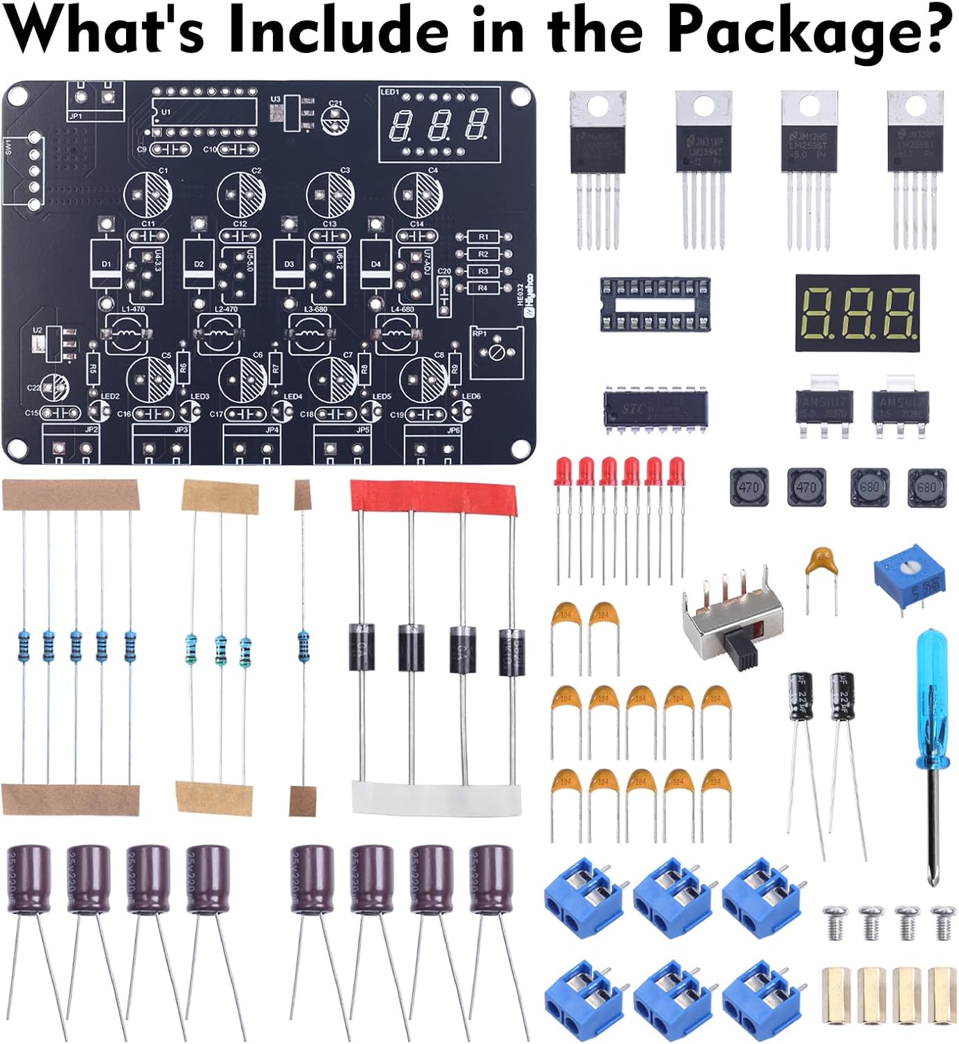
Image: Kit components laid out for inspection.
- Printed Circuit Board (PCB)
- Various Resistors (e.g., 470 Ohm, 680 Ohm)
- Diodes
- Capacitors (Electrolytic and Ceramic)
- LED Indicators
- Integrated Circuits (ICs), including LM2596T-3.3V, LM2596T-5.0V, LM2596T-12V
- Digital Voltage Display Module
- Power Switch
- Adjustable Potentiometer (for ADJ output)
- Terminal Blocks (blue, for input and outputs)
- Inductors
- Small Screwdriver (for terminal blocks)
- Paper Instruction Manual (with color-printed soldering steps)
3. Assembly Instructions
The assembly process involves soldering various electronic components onto the provided Printed Circuit Board (PCB). The kit includes a majority of through-hole components, along with a few surface-mount components (SMCs). Refer to the included paper manual for detailed, color-printed soldering steps and component placement diagrams.
General Soldering Guidelines:
- Preparation: Ensure your soldering iron is clean and properly tinned. Work in a well-ventilated area.
- Identify Components: Carefully identify each component using the provided paper manual and the markings on the PCB. Pay attention to polarity for diodes, LEDs, and electrolytic capacitors.
- Surface-Mount Components (SMCs): If you are new to SMC soldering, it is recommended to watch instructional videos. For this kit, SMCs can typically be mounted using flux, solder, and a heat gun. Apply a small amount of solder to one pad, place the SMC, then heat the pad to melt the solder and position the component. Solder the remaining pads.
- Through-Hole Components: Insert components into their designated holes on the PCB. Bend the leads slightly to hold them in place. Solder each lead from the underside of the board, ensuring a good, shiny solder joint. Trim excess leads after soldering.
- Order of Assembly: Generally, it is best to solder smaller, lower-profile components first (e.g., resistors, diodes), followed by larger components (e.g., capacitors, ICs, terminal blocks, display module, power switch).
- Inspect Joints: After soldering, visually inspect all solder joints for bridges, cold joints, or insufficient solder. Re-solder any problematic connections.

Image: Fully assembled power supply module.
4. Setup
Once the module is fully assembled and all solder joints have been inspected, you can proceed with setting it up for operation.
- Input Power Connection: Locate the 'Input DC' terminal block on the PCB. Connect a DC power source (12V-20V) to these terminals. Ensure correct polarity: positive (+) to 'Vin' and negative (-) to 'GND'.
- Power On: Flip the power switch to the 'ON' position. The digital display should illuminate, showing the current voltage of the adjustable output, and the LED indicators for the fixed outputs should light up if a load is connected.
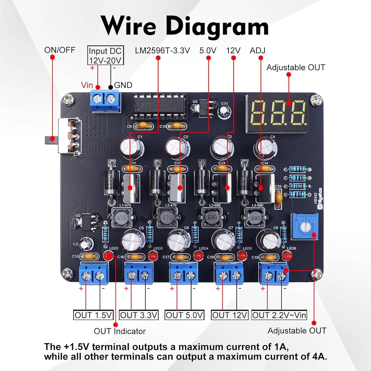
Image: Wire diagram illustrating input and output connections.
5. Operation
The BANRIA Power Supply Module offers multiple output voltages for various electronic projects.
Output Terminals:
- Fixed Outputs: The module provides four fixed voltage outputs: 1.5V, 3.3V, 5.0V, and 12V. Each has a dedicated terminal block. The +1.5V terminal outputs a maximum current of 1A, while all other terminals can output a maximum current of 4A.
- Adjustable Output (ADJ): The fifth output is adjustable. Use the blue potentiometer (trimmer) on the board to set the desired voltage. The digital display will show the current voltage of this output. The adjustable range is approximately 2.2V to Vin (input voltage), with a maximum output of 15.2V when input exceeds 15.2V.
Key Features:
- Power Switch: A dedicated power switch allows for easy on/off control without repeatedly connecting/disconnecting the input power.
- Output Voltage Display: The digital display clearly shows the voltage of the adjustable output. The maximum display error is not greater than 0.45V.
- LED Indicators: Each fixed output has an LED indicator to show activity.

Image: Product details showing the adjustable potentiometer, LED, power switch, and display.
Voltage Characteristics:
- Voltage reduction function: Output voltage is lower than input voltage, with a minimum voltage difference of 0.3V.
- The lower the input voltage, the greater the voltage difference, ranging from 0.1V to 0.3V.
- When the input voltage is below 4V, the brightness of the digital tube display significantly decreases; it completely turns off at 3.8V.
- When the input voltage is below 6.5V, the highest voltage of ADJ reaches 6.5V.
- When the input voltage is below 6.5V, the lowest voltage of ADJ is above 2.2V.
- When the input voltage equals 15V, the ADJ output range is: 2.2V to 14.8V.
- When the input voltage exceeds 15.2V, the maximum voltage output by ADJ is 15.2V.
- When the output voltage is below the normal value, the brightness of the red indicator light will become dim.
6. Maintenance
To ensure the longevity and reliable operation of your power supply module, follow these maintenance guidelines:
- Keep the module clean and free from dust and debris. Use a soft, dry brush or compressed air for cleaning.
- Avoid exposing the module to moisture or extreme temperatures.
- Periodically check solder joints for any signs of cracking or corrosion, especially if the module is frequently moved or subjected to vibrations.
- Ensure proper ventilation around the module during operation to prevent overheating.
7. Troubleshooting
If you encounter issues with your BANRIA Power Supply Module, consider the following troubleshooting steps:
- No Power/Display Off:
- Check the input power source (12V-20V DC) and its connections to the module.
- Ensure the power switch is in the 'ON' position.
- Verify all power-related solder joints (input terminals, power switch, display module) are solid.
- If input voltage is below 3.8V, the display will be off.
- Incorrect Output Voltage:
- For fixed outputs, check the corresponding LM2596T IC and its surrounding components for proper soldering.
- For the adjustable output, ensure the potentiometer is correctly installed and functioning. Rotate it to see if the voltage changes.
- Verify the input voltage is within the specified range (12V-20V).
- No Output/Dim LED:
- Check the solder joints for the specific output terminal and its associated components.
- Ensure no short circuits are present on the output.
- A dim red indicator light may suggest the output voltage is below its normal value.
- Component Overheating:
- Ensure no short circuits are present on the outputs or input.
- Verify that the load connected to the output does not exceed the maximum current rating (1A for 1.5V, 4A for others).
8. Specifications
| Product Dimensions (L x W x H) | 9.91 x 6.81 x 1.98 cm |
| Item Weight | 80 Grams |
| Model Number | EM21559-UK |
| Input Voltage Range | 12V - 20V DC (Max 20V) |
| Fixed Output Voltages | 1.5V, 3.3V, 5.0V, 12V |
| Adjustable Output Voltage Range | Approx. 2.2V to 15.2V (depending on input) |
| Max Output Current (1.5V) | 1A |
| Max Output Current (Other Outputs) | 4A |
| Display Error (Max) | 0.45V |
| Educational Value | Electronics skills, soldering skills, problem-solving skills |
| Assembly Required | Yes |
| Recommended Age | 14 years and up |
9. Warranty and Support
This product is designed for educational and hobbyist use. For any questions regarding assembly, operation, or troubleshooting that are not covered in this manual, please refer to the contact information provided with your purchase or visit the BANRIA official support channels.
Specific warranty details may vary by region and retailer. Please retain your proof of purchase for any warranty claims.


