
Introduction
Thank you for choosing the OBDMONSTER LED Battery Tester and Car Timing Light. This comprehensive tool is designed to assist with automotive diagnostics, specifically for adjusting engine ignition timing and monitoring battery capacity. Please read this manual thoroughly before use to ensure safe and effective operation.
Safety Information
Always observe the following safety precautions when using this device:
- Ensure the vehicle's engine is off and the parking brake is engaged before connecting or disconnecting the device.
- Wear appropriate personal protective equipment, including safety glasses and gloves.
- The power supply for the timing light is 12V. Connect the red clamp to the positive (+) terminal and the black clamp to the negative (-) terminal of the vehicle battery. Incorrect polarity can damage the device.
- When using the timing light, keep hands and clothing clear of moving engine parts, such as belts and fans.
- Ensure proper ventilation when working on a running engine to avoid inhaling exhaust fumes.
- Do not expose the device to moisture or extreme temperatures.
- Keep out of reach of children.
Product Overview
The OBDMONSTER tool combines an engine timing light and an LED battery capacity display. It is designed for use with 12V ignition systems and is suitable for various gasoline engines, including those found in automobiles, motorcycles, ATVs, RVs, and boats.
Key Features:
- Engine Timing Gun: Capable of re-timing ignition for optimal engine performance, supporting speeds up to 1000 RPM.
- Advance Function: Allows intuitive testing and adjustment of ignition timing scales on the engine flywheel or belt pulley. Detects automotive knock suppression and vacuum advance angle control systems.
- Enhanced Brightness: The timing light features 58% increased brightness for clear visibility even in daylight.
- Durable Design: Thickened wires (25% thicker) and an integrated line machine design ensure longevity and stable connections.
- Ergonomic Handle: Pistol-grip design for comfortable operation and easy access to controls.
- Sensor Clips: Sliding clip design for secure and safe connection to the No.1 cylinder's high voltage line.
- Reverse Polarity and Overload Protection: Built-in safeguards prevent damage from incorrect connections or excessive current.
- LED Battery Capacity Display: Features 3-color LED bars (10 bars total) to indicate battery capacity from Empty (E) to Full (F), with each bar representing 10%.
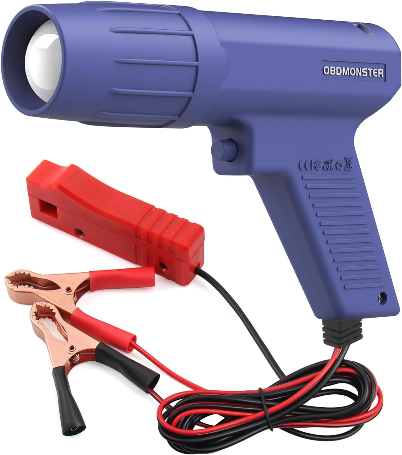
Figure 1: The OBDMONSTER LED Battery Tester and Car Timing Light, showing the timing light gun, battery clamps, and wiring.

Figure 2: Illustration highlighting key features including strong flash, integrated line machine design, high-purity copper alligator clips, ergonomic handle, and overload protection.

Figure 3: Comparison showing 58% brightness enhancement of the timing light and an illustration of reverse polarity and overload protection for the battery connection.
Specifications
| Feature | Specification |
|---|---|
| Brand | OBDMONSTER |
| Model | B0DZGPCVGL |
| Input Voltage (Timing Light) | 12V DC |
| Max Engine Speed (Timing Light) | Up to 1000 RPM |
| Timing Light Brightness | 58% Enhanced |
| Wire Thickness | 25% Thicker |
| Battery Monitor Display | 3-color LED, 10 bars (10% per bar) |
| Compatibility | Automobiles, motorcycles, ATVs, RVs, boats (two-stroke or four-stroke gasoline engines with 12V ignition systems) |
Setup Instructions
A. Timing Light Setup
- Prepare the Vehicle: Ensure the engine is off and cool. Locate the vehicle's battery and the No.1 cylinder's high voltage spark plug wire.
- Connect Power: Attach the red power clamp of the timing light to the positive (+) terminal of the 12V vehicle battery. Attach the black power clamp to the negative (-) terminal of the battery or a suitable ground point on the chassis.
- Connect Inductive Clamp: Clamp the inductive sensor clip onto the high voltage line of the No.1 cylinder. Ensure the arrow on the inductive clamp points towards the spark plug.

Figure 4: Visual guide for connecting the timing light: Step 1 shows connecting the red (+) and black (-) clamps to the battery, and the inductive clamp to the No.1 cylinder wire.
B. Battery Capacity Display Setup
The battery capacity display can be connected in two ways:
- Direct Connection (No Switch): Connect the positive wire of the battery monitor directly to the positive terminal of the 12V battery and the negative wire to the negative terminal. The LED lights will remain on continuously.
- Key Switch Connection (With Switch): For applications where you want the display to turn off with the vehicle, connect the positive wire of the battery monitor to a switched 12V source (e.g., ignition switch output) and the negative wire to the negative battery terminal or chassis ground.
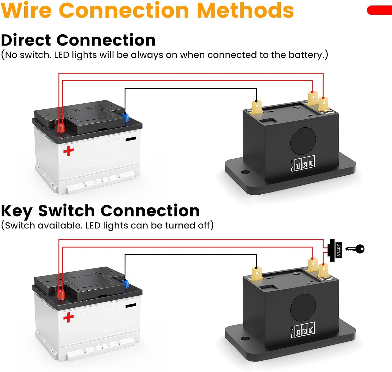
Figure 5: Diagrams illustrating direct connection (LEDs always on) and key switch connection (LEDs turn off with ignition) for the battery capacity display.
Operating Instructions
A. Using the Car Timing Light
- Connect the Timing Light: Follow the "Timing Light Setup" instructions above.
- Warm Up Engine: Start the engine and allow it to reach its normal operating temperature. This ensures accurate timing readings.
- Check Ignition Timing: Aim the timing light at the crankshaft scale of the pulley. Pull the trigger on the timing light gun. The flash will illuminate the timing marks on the pulley, allowing you to read the current ignition timing.
- Compare Readings: If necessary, increase the engine RPM and then release to observe how the timing changes. Adjust the engine's timing according to your vehicle's service manual specifications.
Figure 6: Visual guide for operating the timing light: Steps include warming up the engine, checking ignition timing by aiming at the crankshaft pulley, and comparing readings.
B. Using the LED Battery Capacity Display
Once the battery capacity display is connected according to the "Battery Capacity Display Setup" instructions, it will automatically show the current battery charge level.
- The display features 10 LED bars. Each bar represents 10% of the battery's capacity.
- The colors indicate the charge level:
- Red: Indicates low charge (e.g., 10%).
- Yellow: Indicates medium charge (e.g., 30%).
- Green: Indicates high charge (e.g., 100%).
- Monitor the display regularly to ensure your battery maintains an adequate charge, especially for applications like golf carts, snowmobiles, and marine vessels.

Figure 7: The LED battery capacity display showing 3-color bars, with examples of red (10%), yellow (30%), and green (100%) charge levels.

Figure 8: Illustration showing the wide application of the timing light for trucks, cars, marine vessels, motorcycles, and snowmobiles, indicating 12V input voltage and compatibility with 6V/12V charging systems and spark plugs.
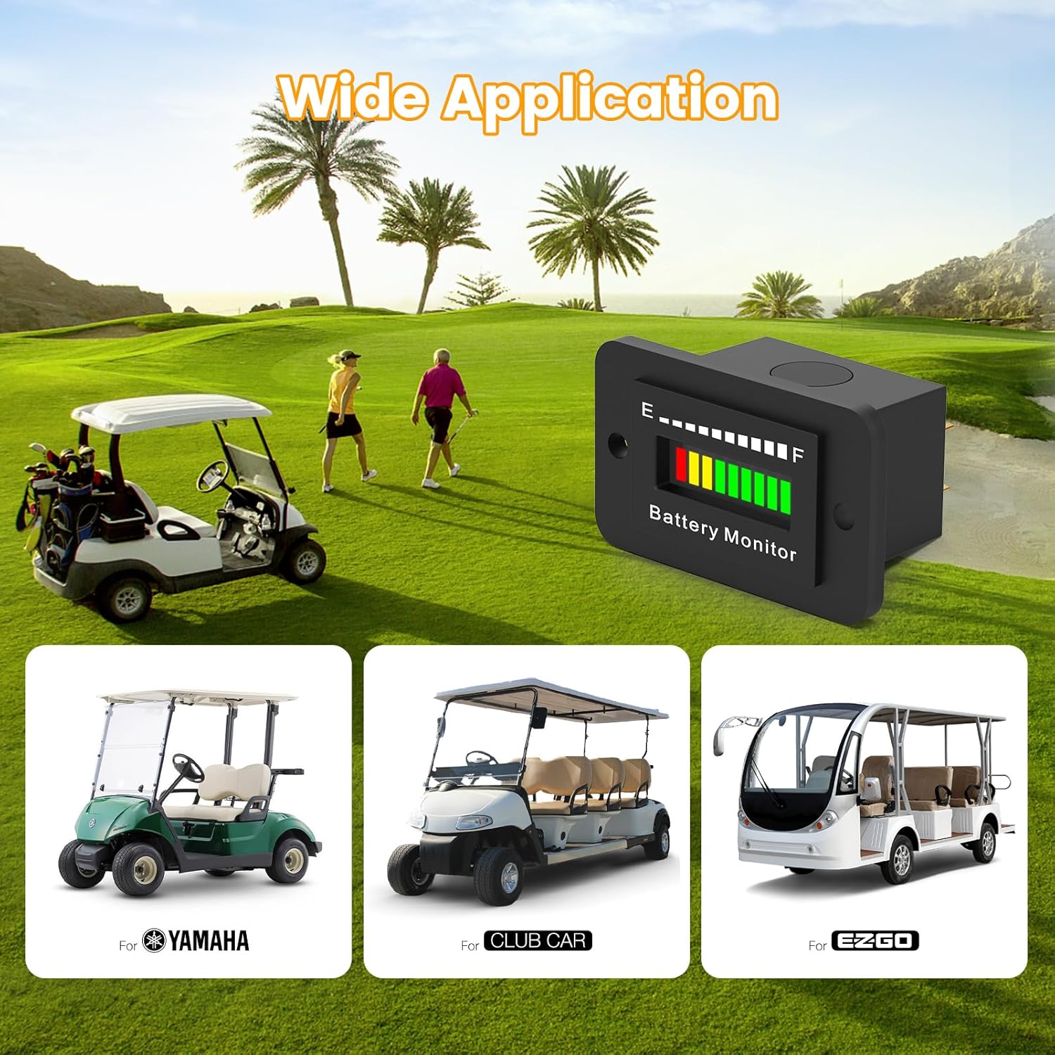
Figure 9: Illustration showing the wide application of the battery monitor for golf carts (Yamaha, Club Car, EZGO).
Maintenance
- Keep the device clean and free from dirt, oil, and grease. Use a soft, dry cloth for cleaning.
- Inspect the cables and clamps regularly for any signs of wear, damage, or corrosion. Replace if necessary.
- Store the device in a dry, cool place away from direct sunlight and extreme temperatures when not in use.
- Do not attempt to disassemble or repair the device yourself. Refer to qualified service personnel.
Troubleshooting
| Problem | Possible Cause | Solution |
|---|---|---|
| Timing light does not flash. |
|
|
| Battery display not lighting up. |
|
|
| Inaccurate timing readings. |
|
|
Warranty and Support
For warranty information or technical support, please refer to the product packaging or contact OBDMONSTER customer service directly. Keep your purchase receipt as proof of purchase.
You can visit the OBDMONSTER Store on Amazon for more information and contact options.