1. Product Overview
The UeeKKoo MLX90640-D55 is a compact, non-contact infrared (IR) array thermal imaging camera. It features a 32x24 pixel resolution and communicates via an I2C interface, supporting data rates up to 1MHz. This module is designed for integration with various microcontrollers and single-board computers, including Raspberry Pi (models 5, 4B, 3B+, 3B, 2B, A+, Zero W/WH, Zero 2 W, Pico 2W), Arduino, and STM32 platforms.
The camera detects infrared radiation emitted by objects within its 55° x 35° field of view. It processes this data to calculate surface temperatures and generate thermal images, making it suitable for industrial control, smart home applications, and high-precision non-contact temperature measurements.
2. Package Contents
Verify that all items listed below are present in your package:
- MLX90640-D55 Thermal Camera Module x1
- PH2.0 4PIN Wire x1

Image 2.1: Contents of the MLX90640-D55 Thermal Camera package, showing the camera module and the connecting wire.
3. Specifications
Key technical specifications for the MLX90640-D55 Thermal Camera:
| Parameter | Value |
|---|---|
| Operating Voltage | 3.3V / 5V |
| Field of View (FOV) | 55° x 35° |
| Communication Bus | I2C (0x33 by default) |
| Current Consumption | < 23mA |
| Absolute Accuracy | ±2°C (ambient temp. 0 ~ 50°C) |
| Refresh Rate | 0.5 ~ 64Hz (0.25 ~ 32FPS) |
| Target Temperature Range | -40 ~ 300°C |
| Dimensions | 28 x 16 mm |
| Operating Temperature | -40 ~ 85°C |
| Mounting Hole Size | 2.0 mm |

Image 3.1: The MLX90640-D55 module alongside its detailed specifications.
4. Key Features
- Sensor: Adopts MLX90640 far-infrared thermal sensor array with 32x24 pixels.
- Communication: I2C interface, configurable for fast mode operation up to 1MHz data rate.
- Voltage Compatibility: Onboard voltage translator supports both 3.3V and 5V operating voltages.
- Thermal Sensitivity: Noise Equivalent Temperature Difference (NETD) of 0.1K RMS at 1Hz refresh rate.
- Frame Rate: Programmable frame rate from 0.5Hz to 64Hz (equivalent to 0.25 to 32 FPS).
- Field of View: Wide 55° x 35° Field of View (FOV).
- Resources: Includes development resources and tutorials for Raspberry Pi, Arduino, and STM32.
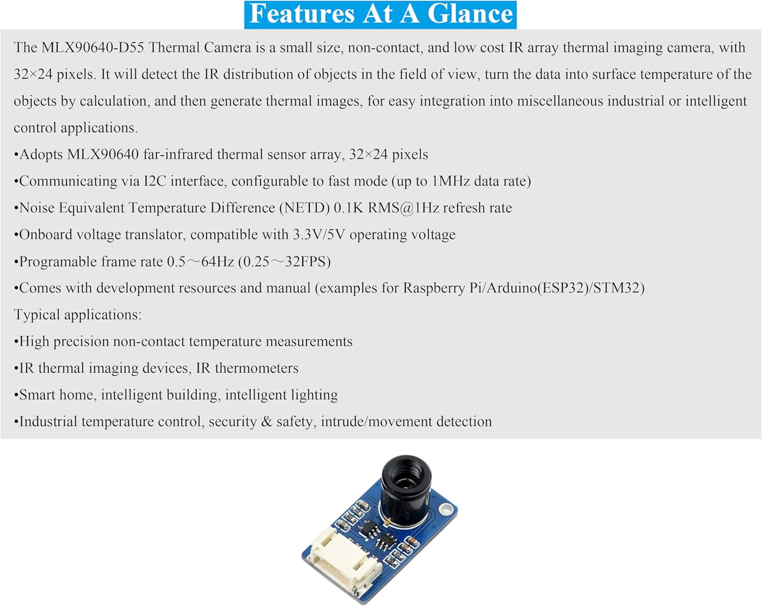
Image 4.1: The MLX90640-D55 module, illustrating its compact design and key components.
5. Setup and Connection
This section details the physical connection of the MLX90640-D55 Thermal Camera to a host board, such as a Raspberry Pi or Arduino.
5.1 I2C Control Interface
The module communicates via the I2C protocol. Ensure your host board supports I2C and connect the pins as described below:
| Pin | Description |
|---|---|
| VCC | 3.3V/5V Power Input |
| GND | Ground |
| SDA | Connects to MCU I2C Data Pin |
| SCL | Connects to MCU I2C Clock Pin |

Image 5.1: The I2C control interface pins on the MLX90640-D55 module.
5.2 Connecting to a Host Board (Example: Raspberry Pi)
To connect the MLX90640-D55 to a Raspberry Pi, use the provided PH2.0 4PIN wire. Match the pins from the camera module to the corresponding GPIO pins on your Raspberry Pi:
- Connect the VCC pin of the camera to a 3.3V or 5V power output pin on the Raspberry Pi.
- Connect the GND pin of the camera to a Ground pin on the Raspberry Pi.
- Connect the SDA pin of the camera to the SDA (I2C Data) pin on the Raspberry Pi (typically GPIO2 for Raspberry Pi).
- Connect the SCL pin of the camera to the SCL (I2C Clock) pin on the Raspberry Pi (typically GPIO3 for Raspberry Pi).
Refer to your Raspberry Pi's GPIO pinout diagram for exact pin locations. Ensure the Raspberry Pi's I2C interface is enabled through its configuration settings.

Image 5.2: The MLX90640-D55 Thermal Camera connected to a Raspberry Pi, demonstrating the wiring setup.
6. Operating Principles
The MLX90640-D55 operates by detecting infrared radiation, which is emitted by all objects with a temperature above absolute zero. The sensor array measures the intensity of this radiation across its 32x24 pixels. Each pixel in the array corresponds to a specific point in the camera's field of view.
The raw infrared data from each pixel is then processed by the module's internal algorithms. These algorithms convert the detected IR intensity into a corresponding surface temperature value for each pixel. By combining these individual temperature readings, a thermal image is generated, representing the temperature distribution of the observed scene.
This non-contact method allows for temperature measurement without physical interaction, making it suitable for applications where direct contact is impractical or undesirable.
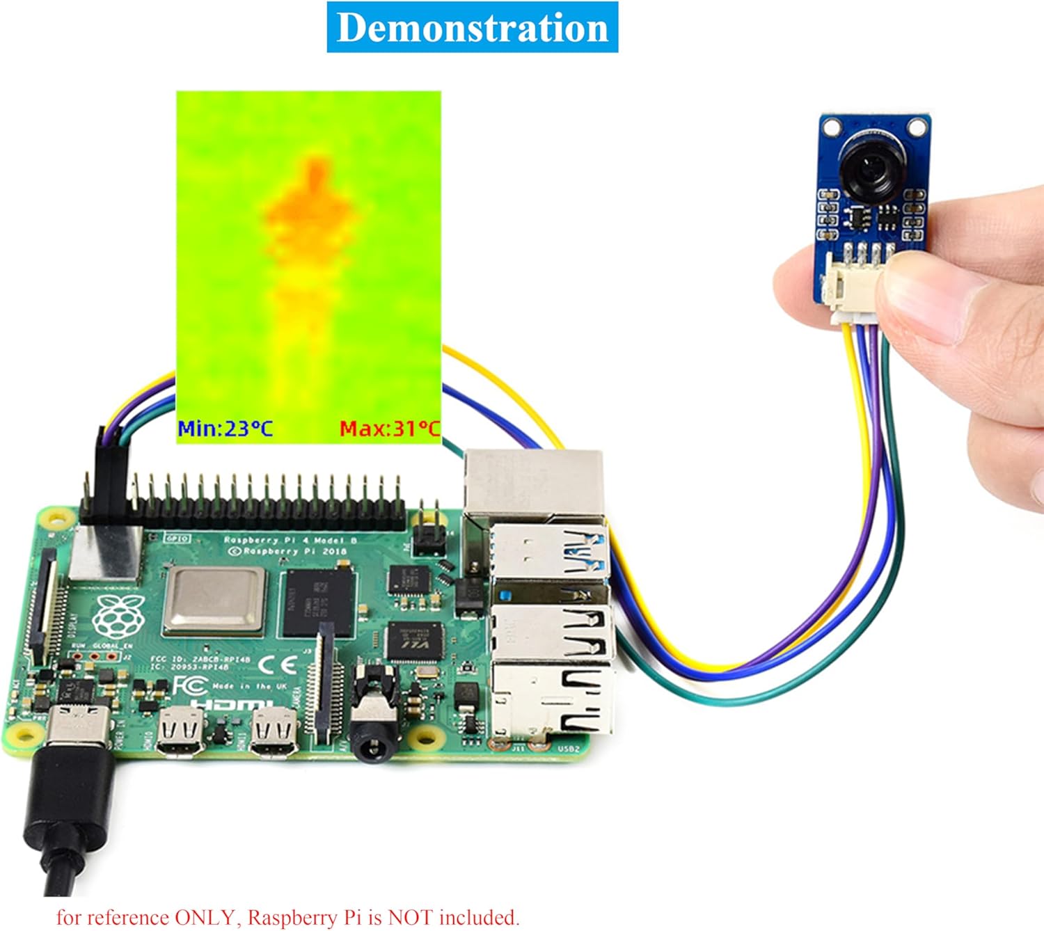
Image 6.1: A thermal image output from the MLX90640-D55, showing temperature variations of a human figure.
7. Applications
The MLX90640-D55 Thermal Camera is suitable for a variety of applications, including:
- High-precision non-contact temperature measurements.
- Integration into IR thermal imaging devices and IR thermometers.
- Smart home and intelligent building systems, including intelligent lighting.
- Industrial temperature control and monitoring.
- Security and safety systems, such as intrusion or movement detection.
8. Development Resources
For detailed programming guides, example code, and further technical documentation, please refer to the official resources provided by UeeKKoo:
Access Development Resources and Tutorials
These resources include examples for Raspberry Pi, Arduino, and STM32, facilitating quick integration and development.
9. Troubleshooting
If you encounter issues with your MLX90640-D55 Thermal Camera, consider the following troubleshooting steps:
- No Data/Incorrect Readings:
- Verify all physical connections (VCC, GND, SDA, SCL) are secure and correctly wired to your host board.
- Ensure the host board's I2C interface is enabled and configured correctly in its operating system or firmware.
- Check the power supply voltage to the module (3.3V or 5V) is stable and within the specified range.
- Confirm the I2C address (default 0x33) is correctly used in your software.
- Software Issues:
- Ensure you are using the correct libraries and example code for the MLX90640 sensor.
- Review your code for any logical errors or incorrect sensor initialization.
- Unstable Readings:
- Environmental factors such as strong air currents or rapid temperature changes in the environment can affect readings.
- Ensure the module is not exposed to direct sunlight or strong heat sources that could interfere with its operation.
- Physical Damage: Inspect the module for any visible signs of damage.
If problems persist after following these steps, consult the online development resources or contact UeeKKoo customer support for further assistance.
10. Outline Dimensions
The physical dimensions of the MLX90640-D55 Thermal Camera module are provided below for integration planning.

Image 10.1: Detailed outline dimensions of the MLX90640-D55 module (Unit: mm).
11. Maintenance
The MLX90640-D55 Thermal Camera module is designed for low maintenance. To ensure optimal performance and longevity:
- Cleaning: Keep the lens free from dust and debris. Use a soft, dry, lint-free cloth for cleaning. Avoid abrasive materials or harsh chemicals.
- Storage: Store the module in a dry, cool environment, away from direct sunlight and extreme temperatures.
- Handling: Handle the module with care to avoid physical shock or damage to the sensitive components. Avoid touching the sensor lens directly.
- Power Supply: Ensure a stable power supply within the specified voltage range (3.3V/5V) to prevent damage.
12. Warranty and Support
For information regarding product warranty, returns, or technical support, please refer to the UeeKKoo official website or contact your point of purchase. Keep your purchase receipt as proof of purchase.
For additional assistance, you may also refer to the development resources linked in Section 8.


