1. Introduction
This manual provides essential information for the safe and efficient use of the CHBMSS FX2N-80MT-001 Programmable Logic Controller (PLC). Please read this manual thoroughly before installation, operation, or maintenance to ensure proper functionality and to prevent damage to the device or injury to personnel. Keep this manual in a safe place for future reference.
2. Product Overview
The CHBMSS FX2N-80MT-001 is an industrial-grade Programmable Logic Controller designed for various industrial automation applications. It features robust industrial processors and a power circuit with anti-reverse and anti-surge protection, making it suitable for reliable signal acquisition and control in demanding environments. This PLC is equipped with an independent programming port for convenient configuration and monitoring.
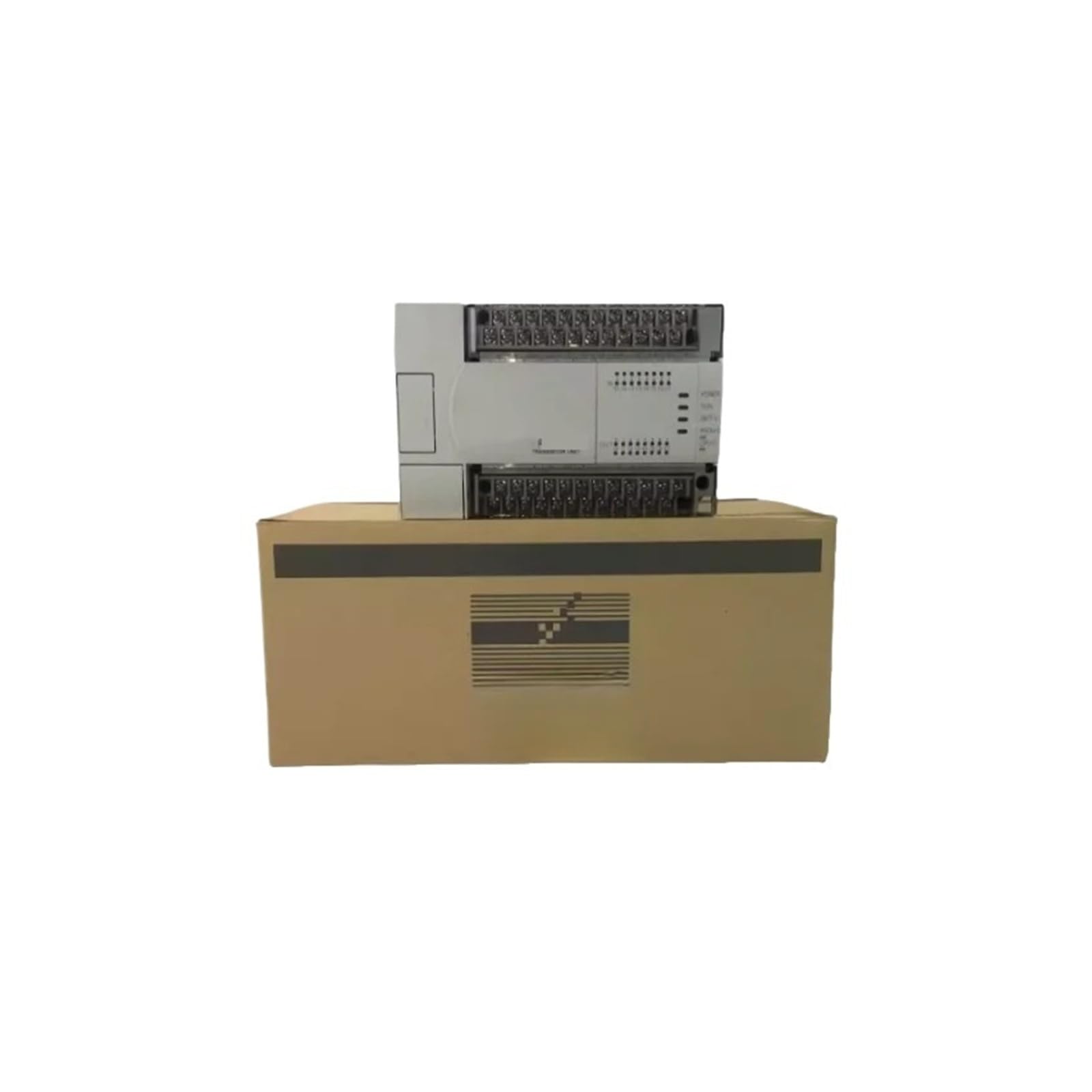
Image: The CHBMSS FX2N-80MT-001 PLC Controller unit shown above its brown cardboard packaging box. The controller features multiple terminal blocks for connections and indicator lights.
3. Safety Information
- Always disconnect power before performing any installation, wiring, or maintenance procedures.
- Ensure that all wiring is correctly connected according to electrical standards and local regulations.
- Do not operate the PLC in environments exceeding its specified temperature, humidity, or vibration limits.
- Only qualified personnel should install, operate, and maintain this device.
- Protect the device from moisture, dust, and corrosive gases.
4. Setup
4.1 Unpacking
Carefully remove the PLC controller from its packaging. Inspect the unit for any signs of damage during transit. If damage is found, contact your supplier immediately.
4.2 Mounting
Mount the PLC securely in a control cabinet or on a DIN rail, ensuring adequate ventilation around the unit to prevent overheating. Refer to the device's dimensions for proper spacing.
4.3 Wiring
- Power Supply: Connect the appropriate DC power supply to the designated power terminals. The power circuit includes anti-reverse and anti-surge protection.
- Input Wiring: Connect your sensors and input devices to the input terminals. Ensure correct polarity and voltage levels.
- Output Wiring: Connect your actuators and output devices to the output terminals. Verify load specifications do not exceed the PLC's output capabilities.
- Programming Port: Connect your programming cable to the independent programming port for software communication.
5. Operating Instructions
5.1 Power On
After all wiring is complete and verified, apply power to the PLC. Observe the power indicator light to confirm the unit is receiving power.
5.2 Programming
Use compatible programming software to develop and download your control logic to the PLC via the independent programming port. Refer to the software's documentation for detailed programming instructions.
5.3 Monitoring and Control
Once programmed, the PLC will execute the control logic, acquiring signals from industrial field equipment and controlling output devices as defined. Monitor the status indicators on the PLC for operational feedback.
6. Maintenance
- Regular Inspection: Periodically inspect the PLC and its wiring for loose connections, dust accumulation, or signs of damage.
- Cleaning: Keep the PLC clean and free from dust. Use a soft, dry cloth for cleaning. Do not use solvents or abrasive cleaners.
- Environmental Control: Ensure the operating environment remains within specified temperature and humidity ranges to prolong the life of the device.
7. Troubleshooting
- No Power Indicator: Check the power supply connection and voltage. Ensure the power circuit breaker is on.
- Communication Issues: Verify the programming cable connection and ensure the correct communication settings are configured in the software.
- Input/Output Malfunction: Check wiring for inputs and outputs. Verify sensor and actuator functionality independently. Review PLC program logic for errors.
- Unexpected Behavior: Review the PLC program for logical errors. Ensure the operating environment is stable and within specifications.
8. Specifications
| Feature | Specification |
|---|---|
| Brand | CHBMSS |
| Model Number | FX2N-80MT-001 |
| Item Weight | 4.41 pounds |
| Package Dimensions | 1.18 x 0.79 x 0.39 inches |
| Assembly Required | No |
| Number of Pieces | 1 |
9. Warranty and Support
Specific warranty terms and detailed support contact information are not provided within the product data. For warranty claims or technical assistance, please contact your original point of purchase or the manufacturer, CHBMSS, directly.


