
1. Introduction
This manual provides essential information for the safe and effective operation of your Gettimore UX-52-100-1.1KW Power Inverter. This device is designed to convert a single-phase 220V AC input into a three-phase 220V AC output, suitable for various three-phase motors and equipment. Please read this manual thoroughly before installation and use, and retain it for future reference.

Figure 1: Front view of the Gettimore UX-52-100-1.1KW Power Inverter, showing the digital display and control buttons.
2. Safety Information
Always observe the following safety precautions to prevent injury or damage to the equipment:
- Electrical Hazard: Installation and maintenance should only be performed by qualified personnel. Ensure power is disconnected before any wiring or inspection.
- Grounding: The inverter must be properly grounded to prevent electric shock.
- Environment: Do not operate the inverter in wet, dusty, or corrosive environments. Ensure adequate ventilation to prevent overheating.
- Overload Protection: Do not exceed the rated power of the inverter or connected motor.
- Emergency Stop: Familiarize yourself with the emergency stop procedures for your system.
3. Product Features
The Gettimore UX-52-100-1.1KW Power Inverter offers the following key features:
- Versatile Input/Output: Converts single-phase 220V input to three-phase 220V output, compatible with various three-phase motors.
- Power Specifications: Rated power of 1100W (1.1KW) with an operating frequency range of 0 to 99 Hz.
- Comprehensive Protection: Includes built-in safeguards against over-voltage, short-circuits, and over-current conditions, ensuring stable performance.
- Intuitive Digital Display: A user-friendly digital display simplifies monitoring and control, allowing for easy parameter adjustments.
- Adaptable Voltage Handling: Supports input voltages ranging from 80V to 280V, providing flexibility in diverse electrical environments.
- Motor Speed Control: Programmable features for precise motor speed regulation.

Figure 2: Inverter front panel illustrating key features such as programmable motor speed control, efficient MPU, and safety protections.
4. Package Contents
Upon opening the package, verify that all items are present and undamaged:
- 1 x Gettimore UX-52-100-1.1KW Power Inverter
- 1 x Remote Control (as depicted in product images)
- 1 x User Manual (this document)
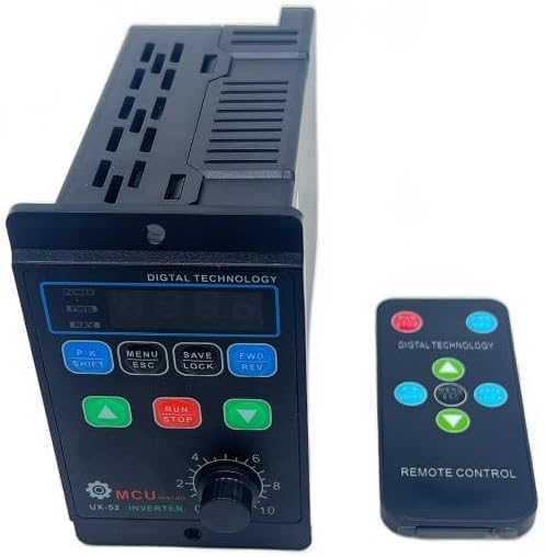
Figure 3: The power inverter shown alongside its included remote control unit.
5. Specifications
| Parameter | Value |
|---|---|
| Brand | Gettimore |
| Model Number | UX-52-100-1.1KW (NZ91663XWBS58TF50088ZYKP0NJN) |
| Input Voltage | Single-phase 80-280V AC |
| Output Voltage | Three-phase 220V AC |
| Rated Power | 1100W (1.1KW) |
| Frequency Range | 0-99 Hz |
| Material | ABS |
| Dimensions (L x W x H) | 147 x 60 x 102 mm (approximate) |
| Item Weight | 429 Grams |
6. Setup and Wiring
Proper wiring is crucial for the safe and correct operation of the inverter. Refer to the wiring diagram below and follow these steps:
- Disconnect Power: Ensure all power sources are disconnected before beginning any wiring.
- Input Power (AC 220V): Connect the single-phase 220V AC input to the terminals labeled N and L on the inverter.
- Ground Connection: Connect the ground wire to the terminal labeled FG. This is essential for safety.
- Motor Output (U, V, W): Connect the three-phase motor wires to the output terminals labeled U, V, and W.
- Control Wiring: If using external control signals (e.g., potentiometer for speed control, external switch for run/stop), connect them to the appropriate terminals (e.g., VI, COM, X1, X2, X3, X4) as per your application requirements. The diagram shows connections for a potentiometer and an external switch.
- Secure Connections: Ensure all wire connections are tight and secure to prevent loose contacts and potential hazards.

Figure 4: Detailed wiring diagram for the inverter, indicating connections for single-phase AC input, ground, three-phase motor output, and external control components.
7. Operating Instructions
The inverter features a digital display and control buttons for easy operation. Refer to the control panel layout for button functions.
7.1 Control Panel Overview
Figure 5: Close-up view of the inverter's control panel, showing the digital display, function buttons, and speed control knob.
- Digital Display: Shows operational parameters such as frequency, speed, and error codes.
- P.K SHIFT Button: Used for parameter shifting or selection.
- MENU ESC Button: Enters/exits menu settings or cancels an operation.
- SAVE LOCK Button: Saves current settings or locks the keypad.
- FWD REV Button: Toggles motor direction (Forward/Reverse).
- UP/DOWN Arrows: Adjust parameter values or navigate menus.
- RUN STOP Button: Starts or stops the motor operation.
- Speed Control Knob: Adjusts the output frequency/motor speed manually.
7.2 Basic Operation
- Power On: After ensuring all wiring is correct and secure, apply single-phase 220V AC power to the inverter. The digital display will illuminate.
- Set Frequency/Speed: Use the speed control knob to set the desired output frequency or motor speed. Alternatively, use the MENU/ESC and UP/DOWN buttons to set parameters digitally.
- Start Motor: Press the RUN STOP button to start the motor. The display will show the operating frequency.
- Change Direction: If needed, press the FWD REV button to change the motor's rotation direction.
- Stop Motor: Press the RUN STOP button again to stop the motor.
- Parameter Adjustment: For advanced settings, refer to the detailed programming guide (if available separately) or use the MENU/ESC button to access parameters and the UP/DOWN arrows to adjust them. Remember to use the SAVE LOCK button to save changes.
8. Maintenance
Regular maintenance helps ensure the longevity and reliable performance of your inverter.
- Cleaning: Keep the inverter clean and free from dust and debris. Use a soft, dry cloth for cleaning. Do not use liquid cleaners.
- Ventilation: Ensure that the ventilation openings and cooling fan are not obstructed. Periodically check and clean the fan to maintain proper airflow.
- Connections: Periodically inspect all wiring connections for tightness and signs of wear or corrosion.
- Environmental Conditions: Ensure the operating environment remains within the specified temperature and humidity ranges.

Figure 6: Side view of the inverter, highlighting the cooling fan for proper heat dissipation.
9. Troubleshooting
If you encounter issues with your inverter, refer to the following common problems and solutions:
- Inverter does not power on:
- Check the input power supply and ensure it is connected correctly.
- Verify that the input voltage is within the specified range (80-280V AC).
- Inspect the power cable for damage.
- Motor does not run:
- Ensure the motor is properly wired to the U, V, W output terminals.
- Check if the RUN/STOP button has been pressed.
- Verify that the frequency setting is not zero.
- Check for any error codes on the digital display and consult the manual for their meaning (if a detailed error code list is provided separately).
- Motor runs erratically or at incorrect speed:
- Check the speed control knob or digital frequency setting.
- Ensure the motor parameters (if programmable) are correctly set for your specific motor.
- Inspect for loose connections or interference.
- Overload or Over-current error:
- Reduce the load on the motor.
- Check for any mechanical issues with the motor or driven equipment that might cause excessive current draw.
- Verify that the inverter's power rating matches the motor's requirements.
For persistent issues or complex problems, contact customer support.
10. Warranty and Support
Information regarding product warranty and customer support details is not available in the provided product data. Please refer to the product packaging or the seller's website for specific warranty terms and contact information for technical assistance.