
1. Introduction
The Hantek 2D72 is a versatile 3-in-1 handheld device combining the functions of a digital oscilloscope, a digital multimeter, and a waveform generator. Designed for ease of use and portability, it is suitable for various applications including electronics learning, diagnosis, repair, and field work.
This manual provides essential information for the safe and effective operation of your Hantek 2D72 device. Please read it thoroughly before use and retain it for future reference.
2. Key Features
- Oscilloscope: 2 channels, 70MHz bandwidth, 250MSa/s (single-channel) / 125MSa/s (dual-channel) sample rate, 10mV-10V vertical resolution.
- Multimeter: Measures AC/DC voltage/current, resistance, diode, capacitance, and continuity. High sensitivity and accuracy.
- Waveform Generator: Generates sine, square, triangular, and trapezoidal waveforms.
- User-Friendly Interface: Simplify operation with automatic measuring functions and adjustable settings.
- Portable Design: Handheld size with a durable, shock-resistant, and heatproof shell.
- Connectivity: PC software support for Windows 7/8/10 (32-bit and 64-bit) for extended functionality.
3. Safety Information
Always observe the following safety precautions to prevent injury and avoid damage to the instrument or connected devices:
- Do not touch any exposed terminals or components when the device is powered on.
- Ensure the correct input range is selected for measurements to prevent overload.
- Use only the probes and accessories supplied or recommended by Hantek.
- Do not operate the device in wet or damp conditions.
- Disconnect power before cleaning or servicing the device.
- Refer to the specifications for maximum input voltage ratings.
4. Package Contents
Verify that all items listed below are present in your package:
- Hantek 2D72 Oscilloscope Unit
- Oscilloscope Probes (x2)
- Multimeter Leads (x2)
- Type-C Charging Cable
- Clip Probes (x2)
- Power Adapter (if included)

Image: Hantek 2D72 Oscilloscope with its standard accessories, including probes, leads, and charging cable.
5. Setup
5.1 Charging the Device
Connect the Type-C charging cable to the device's charging port and the other end to a USB power adapter. The charging indicator will show the charging status. Ensure the device is fully charged before initial use for optimal battery life.
5.2 Powering On/Off
Press and hold the power button located on the side of the device to turn it on or off.
5.3 Connecting Probes/Leads
- Oscilloscope Probes: Connect the BNC connector of the oscilloscope probes to the CH1 and CH2 input jacks. Ensure a secure connection.
- Multimeter Leads: Insert the red lead into the V/Ω/C/+ jack and the black lead into the COM jack for voltage, resistance, capacitance, and diode measurements. For current measurements, refer to the specific current input jacks (mA or A).
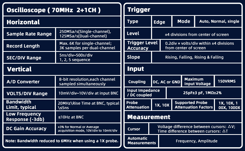
Image: Close-up of the Hantek 2D72 interface, showing input jacks for probes and multimeter leads.
6. Operating Instructions
The Hantek 2D72 features a simple interface with dedicated buttons for mode switching (Scope, DMM, AWG) and navigation.
6.1 Oscilloscope Mode
- Press the Scope button to enter oscilloscope mode.
- Connect the oscilloscope probes to the circuit under test.
- Press the Auto button for automatic waveform setup. This function adjusts vertical scale, horizontal scale, and trigger level.
- Use the Channel button to select between CH1, CH2, or both.
- Adjust vertical sensitivity (VOLTS/DIV) and horizontal time base (SEC/DIV) using the arrow keys.
- Use the Trig button to access trigger settings (Type, Edge, Mode, Level).
- The device supports cursor measurements for voltage difference (ΔV) and time difference (ΔT), and automatic measurements for frequency and amplitude.
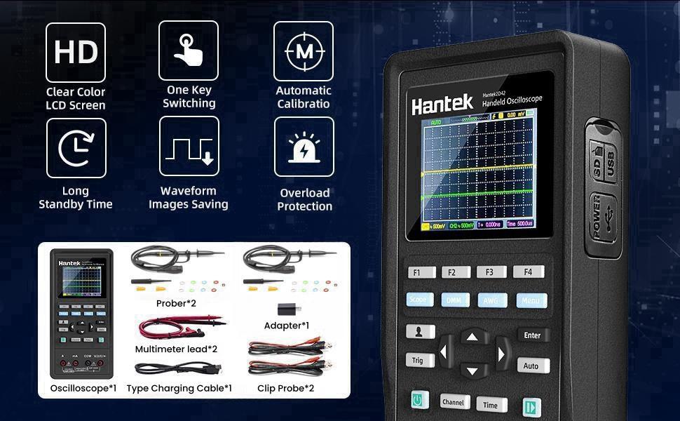
Image: The Hantek 2D72 displaying a waveform on its high-resolution LCD screen, illustrating its oscilloscope function.
6.2 Multimeter Mode
- Press the DMM button to enter multimeter mode.
- Connect the multimeter leads to the circuit or component under test.
- Use the function buttons (e.g., F1, F2, F3, F4) or arrow keys to select the desired measurement type (AC/DC Voltage, AC/DC Current, Resistance, Diode, Capacitance, Continuity).
- The display will show the measurement value.

Image: The Hantek 2D72 displaying a voltage reading in multimeter mode, demonstrating its DMM capabilities.
6.3 Waveform Generator Mode
- Press the AWG button to enter waveform generator mode.
- Connect the output of the waveform generator to the desired circuit.
- Use the function buttons or arrow keys to select the waveform type (Sine, Square, Triangular, Trapezoidal).
- Adjust the frequency and amplitude of the generated waveform using the controls.

Image: The Hantek 2D72 displaying a sine wave in waveform generator mode, indicating its AWG functionality.
7. Maintenance
- Cleaning: Use a soft, dry cloth to clean the device. Do not use abrasive cleaners or solvents.
- Storage: Store the device in a cool, dry place away from direct sunlight and extreme temperatures.
- Battery Care: For long-term storage, charge the battery to approximately 50% every three months to maintain battery health.
- Probe Calibration: Periodically check and calibrate oscilloscope probes as needed to ensure accurate measurements.
8. Troubleshooting
| Problem | Possible Cause | Solution |
|---|---|---|
| Device does not power on. | Low battery or power adapter issue. | Charge the device. Check power adapter and cable. |
| No waveform displayed in oscilloscope mode. | Incorrect probe connection, trigger settings, or vertical/horizontal scale. | Ensure probes are connected correctly. Press 'Auto'. Adjust trigger level, vertical, and horizontal scales. |
| Multimeter readings are inaccurate. | Incorrect lead connection, measurement range, or damaged leads. | Verify lead connections and selected measurement range. Test leads for continuity. |
| Waveform generator output is incorrect. | Incorrect waveform type, frequency, or amplitude settings. | Check and adjust waveform parameters in AWG mode. |
9. Specifications
9.1 Oscilloscope (70MHz, 2+1CH)
| Parameter | Value |
|---|---|
| Sample Rate Range | 250MSa/s (Single-channel), 125MSa/s (Dual-channel) |
| Record Length | Max. 6K for single-channel; 3K samples per dual-channel |
| SEC/DIV Range | 5ns/div - 500s/div (1, 2, 5 sequence) |
| A/D Converter | 8-bit resolution, each channel sampled simultaneously |
| VOLTS/DIV Range | 10mV/div - 10V/div at input BNC |
| Bandwidth Limit | 20MHz (Rise Time at BNC, typical ≤5ns) |
| Low Frequency Response (-3db) | ≤10Hz at BNC |
| DC Gain Accuracy | ±3% for Normal or Average acquisition mode, 10V/div to 10mV/div |
| Input Coupling | DC, AC or GND |
| Maximum Input Voltage | 150VRMS |
| Input Impedance | 25pF±3 pF, 1MΩ±2% |
| Probe Attenuation | 1X, 10X |
| Supported Probe Attenuation Factors | 1X, 10X, 100X, 1000X |
| Trigger Type | Edge |
| Trigger Mode | Auto, Normal, Single |
| Trigger Level | ±4 divisions from center of screen |
| Trigger Level Accuracy | 0.2div × volts/div within ±4 divisions from center of screen |
| Trigger Slope | Rising, Falling, Rising & Falling |
| Cursor Measurement | Voltage difference between cursors: ΔV; Time difference between cursors: ΔT |
| Automatic Measurements | Frequency, Amplitude |
9.2 Digital Multimeter (DMM)
| Parameter | Value |
|---|---|
| Maximum Resolution | 4,000 Counts |
| DMM Testing Modes | Voltage, Current, Resistance, Capacitance, Diode & On-Off |
| Maximum Input Voltage | AC: 600V, DC: 600V |
| Maximum Input Current | AC: 10A, DC: 10A |
| Input Impedance | 10MΩ |
| DC Voltage | 400.00mV-600.0V (±(1% + 5)), Overload protection: 400mV: 250V, other: 600Vrms |
| AC Voltage | 4.000V-600.0V (±(1.5% + 5)), Frequency: 40Hz-400Hz; Frequency of 400V and 600V: 40Hz-100Hz |
| DC Current | 40.00mA-10.00A (±(1-3% + 2)), Self restoring fuse: 200mA/250V, 4A and 10A range no fuse. |
| AC Current | 40.00mA-10.00A (±(1-3% + 5)), Frequency: 40Hz-400Hz; Self restoring fuse: 200mA/250V, 4A and 10A range no fuse. |
| Resistance | 400.0Ω-40.00MΩ (±(1.5% + 5)), Overload protection: 220Vrms |
| Capacitance | 40.00nF-100.0uF (±(3% + 5)), Overload protection: 220Vrms |
| Diode | 0V-1.0V |
| On-Off Test | <50Ω |
9.3 Waveform Generator
| Parameter | Value |
|---|---|
| Waveform Frequency (Sine) | 1Hz-25MHz |
| Waveform Frequency (Square) | 1Hz-10MHz |
| Waveform Frequency (EXP) | 1Hz-5MHz |
| Waveform Frequency (Ramp) | 1Hz-1MHz |
| Sampling Rate | 250MSa/s |
| Frequency Resolution | 0.10% |
| Waveform Depth | 512Sa |
| Vertical Resolution | 12 bit |
| Output Impedance | 50 Ω |
| Amplitude | 2.5Vpp(50Ω), 5Vpp(High impedance) |
9.4 General Specifications
| Parameter | Value |
|---|---|
| Power Supply Voltage | 100V~240VAC, 50Hz-60Hz; DC INPUT: 5VDC, 2A |
| Power Consumption | <2.5W |
| Fuse | T, 3A |
| Environmental Humidity | 10℃~40℃ (≤90% relative humidity), 10℃~122℉ (≤60% relative humidity) |
| Environmental Altitude | Operating and Non-operating: 3,000m (10,000 feet) |
| Mechanical Shock (Random Vibration) | 0.31grms from 50Hz to 500Hz, 10 minutes on each axis |
| Mechanical Shock (Non-operating) | 2.46grms from 5Hz to 500Hz, 10 minutes on each axis |
| Mechanical Shock (Operating) | 50g, 11ms, half sine |
| Item Weight | 14.4 ounces |
| Item Dimensions | 7.8 x 1.6 x 4 inches |
10. Warranty and Support
Hantek products are designed for reliability and performance. For warranty information, please refer to the documentation provided with your purchase or contact your retailer.
For technical support, software downloads, or further assistance, please visit the official Hantek website or contact their customer service. You can also visit the Hantek Store on Amazon for product information and support resources.