1. Introduction
This manual provides detailed instructions for assembling and operating your IS RGB 4-Digit DIY Clock Soldering Kit. This kit is designed as an educational project to develop soldering skills and understand basic electronics, resulting in a functional digital clock with various display features and colorful LED lights.

Image 1: The fully assembled IS RGB 4-Digit DIY Clock.
2. Safety Information
Please read and understand all safety warnings before beginning assembly. This kit involves soldering, which requires caution.
- Always work in a well-ventilated area to avoid inhaling solder fumes.
- Wear appropriate eye protection (safety glasses) to protect against splashes or flying debris.
- Use a soldering iron with care; it operates at high temperatures and can cause burns.
- Ensure the soldering iron is placed in a safe holder when not in use.
- Keep flammable materials away from the soldering area.
- Wash hands thoroughly after handling solder, especially lead-based solder.
- Keep components and tools out of reach of children and pets.
3. Package Contents
Verify that all components listed below are present in your kit before starting assembly. Refer to the image for visual confirmation.

Image 2: All components included in the soldering kit, laid out for inspection. This includes PCBs, resistors, capacitors, LEDs, buttons, and a USB cable.
Your kit should contain:
- Printed Circuit Boards (PCBs)
- Resistors (various values)
- Capacitors (electrolytic and ceramic)
- RGB LEDs (frosted)
- 8x8 Dot Matrix Screens
- Push Buttons ('Set', 'Save', '+', '-')
- Speaker
- Integrated Circuits (ICs) and sockets
- Diodes
- Transistors
- USB Power Cable
- Mounting hardware (screws, standoffs)
4. Assembly Instructions (Soldering Project)
This section guides you through the assembly process. A basic understanding of soldering is recommended. Refer to the detailed printed instruction manual included in your kit for specific component placement and values.

Image 3: An example of soldering practice, highlighting the educational aspect of the kit.
4.1 General Soldering Tips
- Heat both the component lead and the PCB pad simultaneously.
- Apply a small amount of solder to the heated joint.
- Remove the solder, then the iron, ensuring a shiny, cone-shaped joint.
- Avoid cold solder joints (dull, lumpy appearance) or solder bridges (solder connecting two unintended pads).
4.2 Assembly Steps (General Order)
It is generally recommended to solder components from lowest profile to highest profile. This makes the process easier and prevents damage to taller components.
- Resistors and Diodes: Identify values and polarity (for diodes) and solder them into their designated positions.
- Capacitors: Pay attention to polarity for electrolytic capacitors.
- Integrated Circuit (IC) Sockets: Solder the sockets first, then insert the ICs carefully after all soldering is complete to prevent heat damage.
- Push Buttons: Solder the 'Set', 'Save', '+', and '-' buttons.
- RGB LEDs: These require careful soldering due to their small size and multiple contacts. Ensure correct orientation.
- 8x8 Dot Matrix Screens: Solder these display modules.
- Speaker: Solder the speaker connections.
- Power Port: Solder the USB power input port.
- Final Assembly: Once all components are soldered, carefully assemble the PCBs and any casing using the provided screws and standoffs.
After assembly, double-check all solder joints for continuity and absence of shorts before applying power.
5. Operating Instructions
This section details how to use your assembled RGB 4-Digit DIY Clock.
5.1 Powering On
Connect the provided USB cable to the power port on the clock and plug the other end into a 5V USB power adapter (not included) or a computer USB port. The clock will power on and display the current time or the last saved display mode.

Image 4: The clock powered via USB, illustrating its power-off memory feature.
5.2 Display Modes
The clock supports multiple display modes. Press the "Save" button to cycle through the available displays:
- Time (24-hour format)
- Year
- Date (MMDD format)
- Day of the Week
- Temperature (Celsius)

Image 5: The clock showcasing its five different display modes: time, year, date, day of the week, and temperature.
Watch the video below to see the display modes in action:
Video 1: Demonstration of the clock cycling through its various display modes (time, date, week, temperature).
5.3 Setting Clock Functions
Press the "Set" button to enter the setting mode. Use the "+" and "-" buttons to adjust values. Press "Set" again to confirm and move to the next setting. Press "Save" to exit setting mode and save changes.

Image 6: The clock displaying its six function settings: setting time, year, date, week, alarm clock, and alarm sounds.
The available settings include:
- Set the time
- Set the year
- Set the date
- Set the day of the week
- Set the alarm clock time
- Set the alarm sounds (3 melodious tunes available)
The video below demonstrates how to access and adjust these settings:
Video 2: A demonstration of navigating through the clock's setting modes to adjust time, date, and alarm features.
5.4 Colorful LED Lights
The clock features 24 frosted RGB LED lights that display dynamic color transitions. You can turn these lights on or off as desired.

Image 7: The clock's upper section illuminated with vibrant, changing LED colors.
To control the LED lights, use the dedicated buttons on the side of the clock. One button typically turns the lights on, and another turns them off. Refer to the markings on your PCB for exact button functions.
Video 3: A demonstration of turning the colorful LED flashing lights on and off.
5.5 Alarm Function
The clock includes an alarm function with three selectable melodious tunes. Set the alarm time and choose your preferred tune in the setting mode (see Section 5.3).
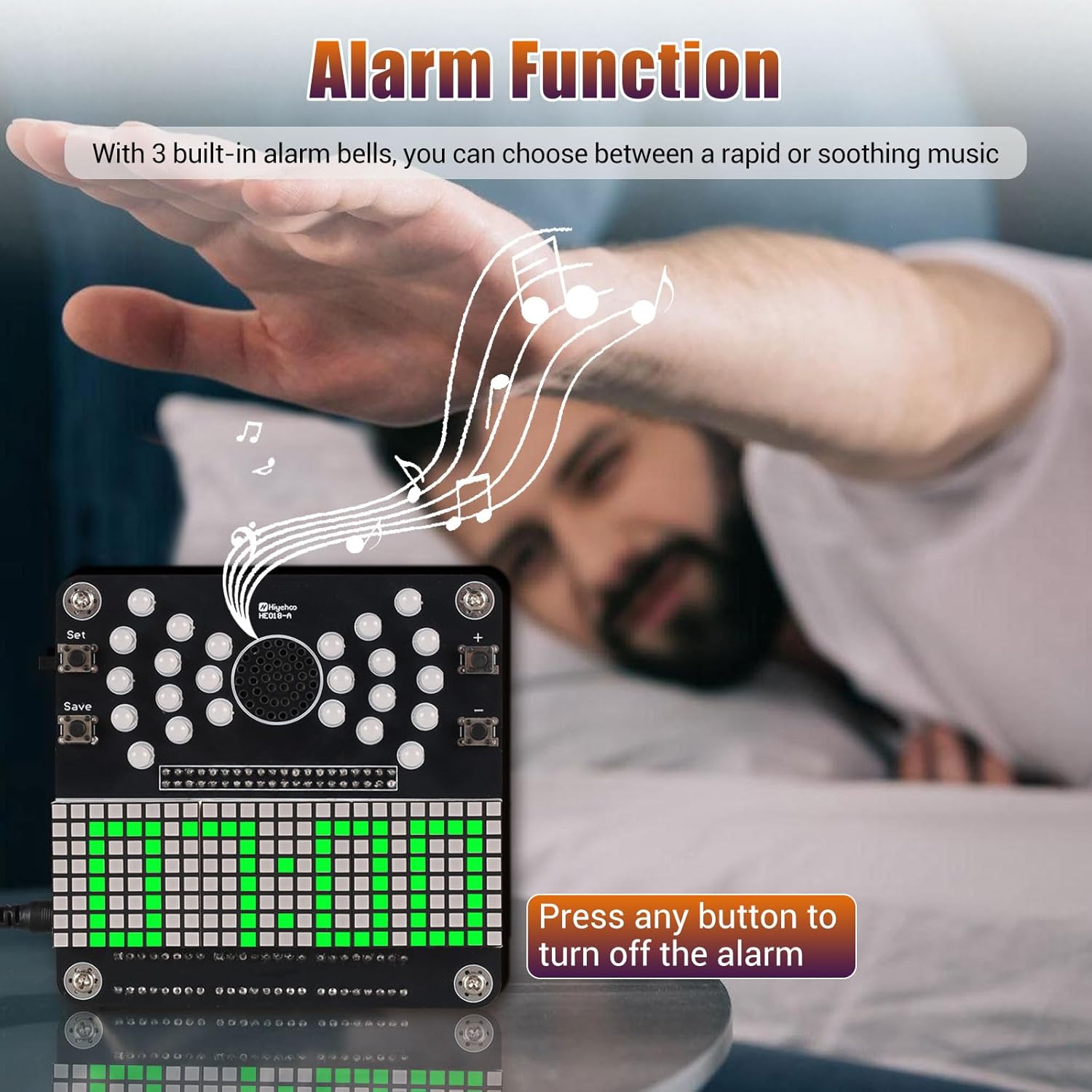
Image 8: A visual representation of the alarm function, showing a hand reaching to press a button to silence the alarm.
When the alarm sounds, press any button on the clock to silence it.
5.6 Power-Off Memory Function
The clock retains its settings (time, date, alarm, etc.) even when power is disconnected. Upon reconnection, it will automatically restore the accurate local time and previous settings without requiring manual reset.
6. Maintenance
- Cleaning: Use a soft, dry cloth to clean the clock. Avoid abrasive cleaners or solvents.
- Storage: Store the clock in a dry environment, away from direct sunlight and extreme temperatures.
- Component Replacement: If any components fail, they can be replaced by desoldering the faulty part and soldering a new one. This requires advanced soldering skills.
7. Troubleshooting
| Problem | Possible Cause | Solution |
|---|---|---|
| Clock does not power on. | No power, faulty USB cable, incorrect soldering of power port. | Ensure USB cable is securely connected and power source is active. Check power port solder joints. |
| Display is blank or shows incorrect characters. | Faulty dot matrix screen, incorrect soldering of display connections, IC not seated correctly. | Inspect solder joints for the display modules and IC sockets. Ensure ICs are fully seated. |
| LED lights do not illuminate or show incorrect colors. | Incorrect LED polarity, faulty LED, poor solder joint on LED. | Verify LED orientation and solder connections. Replace faulty LEDs if necessary. |
| Buttons are unresponsive. | Poor solder joint on button, faulty button. | Check solder connections for the buttons. |
| Alarm does not sound. | Speaker not connected, alarm not set, faulty speaker. | Ensure speaker is correctly soldered. Verify alarm settings. |
8. Specifications

Image 9: Dimensions of the assembled clock, showing a width of 3.74 inches, height of 3.74 inches, and depth of 0.83 inches.
- Brand: IS
- Model Number: GY21504-1
- Display Type: Digital (8x8 Dot Matrix)
- LEDs: 24 Frosted RGB Flashing Lights
- Functions: Time (24-hour), Year, Date, Day of Week, Temperature, Alarm
- Power Source: DC 5V (via USB)
- Memory: Power-off memory function
- Material: Plastic (frame), Electronic Components
- Product Dimensions: Approximately 3.74"W x 3.74"H x 0.83"D
- Item Weight: 7.8 ounces
- Indoor/Outdoor Usage: Indoor
9. Customer Support
For further assistance, technical support, or inquiries regarding your IS RGB 4-Digit DIY Clock Soldering Kit, please contact ICSTATION customer service. Refer to the contact information provided with your purchase or visit the official ICSTATION store on Amazon.
ICSTATION Store: Visit the IS Store on Amazon