
1. Introduction
The PDDAXLQUE DX-GP10 is a high-precision GNSS (Global Navigation Satellite System) module designed for accurate positioning. It supports multi-constellation satellite systems including GPS, BDS (BeiDou), and GLONASS, enabling reliable positioning even in challenging environments. This manual provides detailed instructions for setting up, operating, and maintaining your DX-GP10 module.

Figure 1: DX-GP10 GNSS Module supporting GPS, GLONASS, and BDS. The image illustrates a ship receiving signals from GPS, GLONASS, and BDS satellites, highlighting the module's multi-system capability.
2. Key Features
- Multi-System Positioning: Supports GPS, BDS, and GLONASS for enhanced positioning success rates, especially in complex environments.
- High Precision: Positioning accuracy of less than 2 meters (CEP) and speed accuracy less than 0.1 m/s.
- Fast Satellite Acquisition: Rapid satellite search and Time To First Fix (TTFF) for quick operation.
- Low Power Consumption: Designed for efficiency with high sensitivity.
- Excellent Antenna Design: Equipped with a ceramic antenna for strong signal reception in various environments.
- Active Antenna Detection & Short-circuit Protection: Improves device stability and reduces maintenance.
- Standard Communication Interface: UART interface for easy integration.
- NMEA 0183 Protocol Support: Compatible with most navigation and mapping software.
- Compact Size: Module dimensions are 30mm (L) x 25mm (W) x 7.2mm (H).
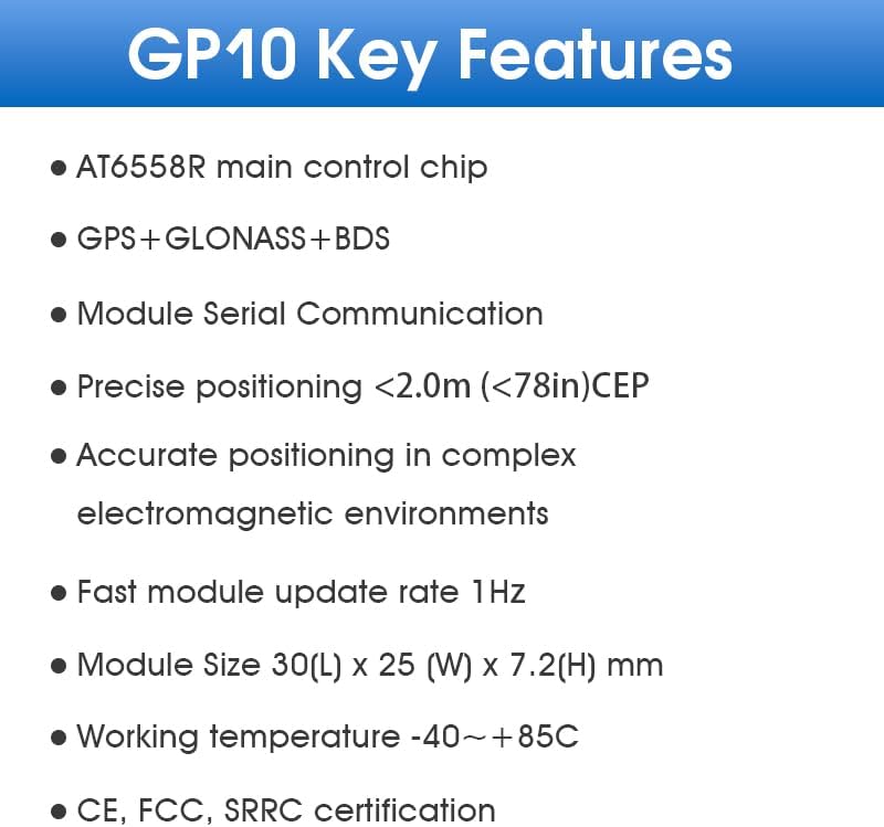
Figure 2: Key Features of the DX-GP10 Module. This image lists the main technical specifications and capabilities of the module, such as the AT6558R main control chip, multi-constellation support, and precise positioning accuracy.

Figure 3: High Anti-Interference Capability. This image highlights the module's built-in advanced anti-jamming unit, ensuring reliable and accurate positioning even in complex electromagnetic environments.
3. Setup and Installation
3.1. Component Identification
The DX-GP10 module typically includes the main GNSS module and an adapter board for easier integration. Identify the following pins on the module/adapter board:
- 1PPS: System Single Pulse Output Indicator.
- RXD: Data Receive Pin.
- TXD: Data Transmit Pin.
- GND: Ground.
- VCC: Power Supply (5V recommended).
- WAKE: Wake-up pin. Pull down to enter standby mode. Default high when not in use.
3.2. Wiring Diagram
Connect the DX-GP10 module to your development board (e.g., Arduino, Raspberry Pi) using the UART interface. Ensure correct polarity for all connections.

Figure 4: GP10 & Adapter Board Wiring Diagram. This diagram illustrates how to connect the DX-GP10 module to an adapter board, showing the pin assignments and recommended connections for power and data.
- Connect the TXD pin of the DX-GP10 module to the RX pin of your development board.
- Connect the RXD pin of the DX-GP10 module to the TX pin of your development board.
- Connect the GND pin of the DX-GP10 module to the GND pin of your development board.
- Connect the VCC pin of the DX-GP10 module to a 5V power supply from your development board.
- The 1PPS pin provides a pulse per second output after successful positioning.
- The WAKE pin can be pulled low to enter standby mode. If not used, leave it unconnected (default high).
Note: The module and the adapter board should be inserted with positive and negative pins correctly aligned.
4. Operating Instructions
4.1. Initial Power-Up and Satellite Acquisition
After connecting the module to your development board and providing power, the module will begin searching for satellite signals.
- Outdoor Use: For optimal performance, operate the DX-GP10 module in an open and unobstructed outdoor area.
- LED Indicator: The LED on the module will flash when satellite signals are detected and a position fix is achieved.
- First Fix Time: Hot start (re-acquisition after a short power-off) typically takes less than 1 second. Cold start (first acquisition or after a long power-off) may take up to 32 seconds.

Figure 5: Fast Positioning Capability. This image displays a satellite positioning interface, demonstrating the module's ability to quickly acquire signals and achieve high accuracy even in challenging signal conditions.
4.2. Data Output
The DX-GP10 module outputs positioning data via its UART interface using the NMEA 0183 protocol. You can read this data using a serial terminal or by programming your development board to interpret the NMEA sentences.
The module provides a 1 Hz update rate for position data.
5. Specifications
5.1. Physical Dimensions
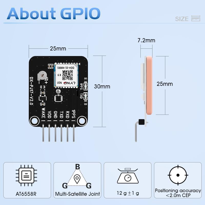
Figure 6: Module Dimensions. This image provides a visual representation of the DX-GP10 module's physical size, including its length (30mm), width (25mm), and height (7.2mm), along with its weight (12g ± 1g).
5.2. Technical Parameters
| Parameter | Value |
|---|---|
| Main Control Chip | AT6558R |
| Supported Constellations | GPS, GLONASS, BDS (BeiDou) |
| Horizontal Positioning Accuracy (CEP) | < 2.0 meters |
| Speed Accuracy | < 0.1 m/s |
| Update Rate | 1 Hz |
| Max. Height | 18000 m |
| Max. Speed | 515 m/s |
| Max. Acceleration | 4 G |
| Hot Start (TTFF) | < 1 s |
| Cold Start (TTFF) | < 32 s |
| Cold Start Recapture Sensitivity | -148 dBm |
| Recapture Sensitivity | -160 dBm |
| Traceability Sensitivity | -162 dBm |
| Working Temperature | -40°C to +85°C |
| Module Dimensions (L x W x H) | 30mm x 25mm x 7.2mm |
| Weight | 12g ± 1g |
| Certifications | CE, FCC, SRRC |

Figure 7: Detailed Specifications. This image provides a comprehensive table of the module's performance parameters and physical characteristics.
6. Maintenance
The DX-GP10 module is designed for durability and requires minimal maintenance.
- Environmental Conditions: Avoid exposing the module to extreme temperatures, humidity, or corrosive substances beyond its specified operating range.
- Physical Handling: Handle the module with care to prevent physical damage. The ceramic antenna is robust but can be damaged by excessive force.
- Cleaning: If necessary, gently clean the module with a dry, soft cloth. Do not use liquid cleaners.
- Antenna Calibration: If the module has scratches or has been subjected to significant physical stress, antenna signal calibration might be required to ensure optimal performance.
7. Troubleshooting
- No Satellite Fix:
Issue: The LED indicator is not flashing, and no position data is received.
Solution: Ensure the module is used in an open outdoor area with a clear view of the sky. Indoor use or adverse weather conditions can significantly affect satellite signal reception. Check all wiring connections, especially power (VCC and GND) and UART (RXD, TXD).
- Inaccurate Positioning:
Issue: The reported position is not accurate or drifts significantly.
Solution: Verify that the module has a strong signal (LED flashing consistently). Ensure there are no large obstructions (buildings, dense foliage) nearby. Electromagnetic interference can also affect accuracy; try relocating the module. If the module has physical damage, antenna calibration may be needed.
- No Data Output via UART:
Issue: The development board is not receiving any data from the module.
Solution: Double-check the RXD/TXD connections (TXD of module to RX of board, RXD of module to TX of board). Ensure the baud rate configured on your development board matches the module's baud rate (default is usually 9600 or 115200, refer to specific module documentation if available). Verify the module is powered correctly (5V).
- Module Not Powering On (No LED Activity):
Issue: The module shows no signs of activity after power connection.
Solution: Confirm that the 5V power supply is correctly connected to the VCC and GND pins and is providing sufficient current. Check for any short circuits or incorrect wiring.
8. Warranty and Support
PDDAXLQUE stands by the quality of its products. For technical support, warranty claims, or any questions regarding the DX-GP10 GNSS module, please contact our customer service.
As a manufacturer, we offer comprehensive technical assistance and support for OEM and ODM services. Please refer to the product packaging or our official website for the most current contact information.
Additional documentation, including product specifications, module pinout, module dimensions, package diagrams, hardware design references, serial test tools, and AT command sets, may be available upon request or through our support channels.

Figure 8: Technical Documentation and Support. This image highlights the availability of professional technical documentation and the manufacturer's commitment to support.