1. Introduction
This manual provides essential information for the setup, operation, and maintenance of the eletechsup ESP32 Expansion Board, Model ES33B08. This board is designed to extend the capabilities of a 38-pin ESP32 development board, offering a versatile platform for industrial automation, smart home projects, and various DIY applications. It integrates WiFi, RS485 communication, multiple analog and digital inputs, and 300MA Darlington tube outputs.
Important Note: The PWR LED does not illuminate upon power-on. Its state is controlled by an IO port of the ESP32.
2. Product Features
- Working Voltage: DC 12V-24V.
- Working Current: Standby current (Digital tube OFF) 15MA, Standby current (Digital tube ON) 50MA.
- On-board Resources:
- 1x RS485 Interface.
- 8x Opto-isolated Digital Inputs (low level trigger, NPN type).
- 4x 0/4-20MA Current Inputs.
- 4x 0-5V/10V Voltage Inputs.
- 4x User-programmable Buttons.
- 1x 4-bit Digital Tube Display.
- 1x Slot for 38-pin ESP32 Development Board.
- 8x 300MA Darlington Tube Outputs.
- Connectivity: Supports WiFi, RS485, MQTT, and Ethernet (via ESP32).
- Applications: Suitable for custom delay timer functions, WIFI remote control, current/voltage collection, home automation, and RS485 master/slave device control.
3. Setup Instructions
The ES33B08 expansion board requires a 38-pin ESP32 development board to function. Ensure the ESP32 board is correctly inserted into the designated slot before applying power.
3.1 Component Identification
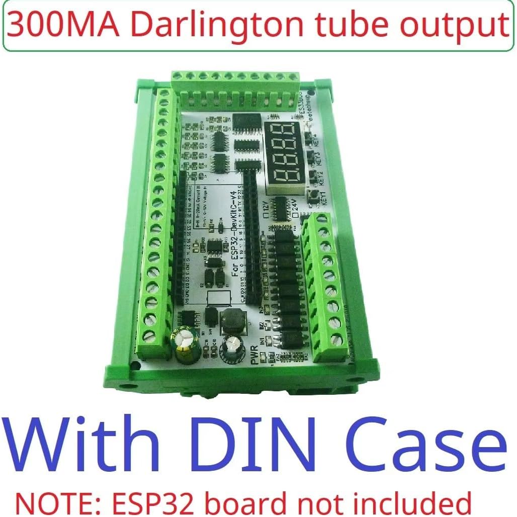
Figure 1: Labeled components of the ES33B08 ESP32 Expansion Board. This image highlights the 1x ESP32 slot, power interface (DC 12V/24V), RS485 interface, 8x 3-24V NPN Digital Inputs, 4x 0/4-20MA Current Inputs, 4x 0-5V/10V Voltage Inputs, 4x Buttons, 1x 4-bit Digital Tube Display, and 8x 300MA Darlington Tube Outputs.
3.2 Power Connection
Connect a DC 12V-24V power supply to the designated power interface terminals. Observe correct polarity. The board is designed to operate within this voltage range.
3.3 ESP32 Board Installation
Carefully insert your 38-pin ESP32 development board into the central ESP32 slot on the expansion board. Ensure all pins are correctly aligned and seated to prevent damage.
Note: The ESP32 board is not included with the expansion board and must be purchased separately.
3.4 Input/Output Connections
Connect your sensors, actuators, and communication lines to the appropriate terminals:
- Digital Inputs: Connect NPN type sensors to the 8 opto-isolated digital input terminals.
- Current Inputs: Connect 0/4-20mA current sources to the 4 current input terminals.
- Voltage Inputs: Connect 0-5V or 0-10V voltage sources to the 4 voltage input terminals.
- RS485: Connect RS485 devices to the A+ and B- terminals of the RS485 interface.
- Darlington Outputs: Connect loads requiring up to 300MA to the 8 Darlington tube output terminals.
4. Operating Instructions
Operation of the ES33B08 expansion board is primarily achieved through custom programming of the integrated 38-pin ESP32 development board. The expansion board provides the hardware interface for various industrial and home automation tasks.
4.1 Programming the ESP32
This expansion board is designed for users to write their own ESP32 code. We provide basic VSCode examples for hardware testing. Advanced functionalities, such as specific delay timers, remote control, or data acquisition, require custom code development.
Disclaimer: We provide limited code examples for hardware testing only. Additional code and technical support for custom applications are not provided.
4.2 Example Applications
With appropriate ESP32 programming, this board can be used for:
- WIFI remote control switches.
- WIFI current and voltage data collection.
- Home automation and smart home DIY projects.
- RS485 Master-Slave device communication (e.g., controlling other RS485 devices).
- Motor forward and reverse control.
- Timing ON/OFF functions, power-up delays, trigger delays, and various cyclic delays.
- Power sequencing.
4.3 RS485 Master Device Application
The board can function as an RS485 master device, replacing traditional PLCs, PCs, or touch screens to control various RS485 slave devices. This requires custom programming on the ESP32 to implement the desired communication protocols and control logic.

Figure 2: Application diagram showing the ESP32 Expansion Board as an RS485 master, interfacing with a PLC and HMI via an RS485 bus. This demonstrates its capability to control various RS485 slave devices.
5. Maintenance
The eletechsup ESP32 Expansion Board is designed for durability and requires minimal maintenance. Follow these guidelines to ensure optimal performance and longevity:
- Cleaning: Keep the board free from dust and debris. Use a soft, dry brush or compressed air for cleaning. Avoid using liquids or solvents.
- Environmental Conditions: Operate the board within its specified temperature and humidity ranges. Avoid exposure to extreme temperatures, moisture, or corrosive environments.
- Connections: Periodically check all wiring connections to ensure they are secure and free from corrosion. Loose connections can lead to intermittent operation or damage.
- Firmware Updates: Regularly check for firmware updates for your ESP32 development board, as these may improve performance or add new features.
6. Troubleshooting
If you encounter issues with your ESP32 Expansion Board, refer to the following troubleshooting tips:
- Board Not Powering On:
- Verify that the DC 12V-24V power supply is correctly connected and providing the specified voltage.
- Ensure the ESP32 board is properly seated in its slot.
- Remember that the PWR LED is controlled by the ESP32's IO port and may not light up immediately upon power-on.
- Inputs Not Responding:
- Check wiring for all input sensors and ensure they are correctly connected to the appropriate terminals.
- Verify that your ESP32 code is correctly configured to read the specific input channels.
- For analog inputs (current/voltage), the acquisition accuracy is determined by the ESP32 board. Consider collecting multiple samples and averaging for more stable readings.
- Outputs Not Activating:
- Confirm that your ESP32 code is correctly controlling the Darlington tube output pins.
- Check the load connected to the outputs to ensure it does not exceed the 300MA current rating per channel.
- Verify that the external load is correctly wired and functioning.
- RS485 Communication Issues:
- Check the A+ and B- wiring for correct polarity and secure connections.
- Ensure the RS485 slave devices are correctly addressed and configured.
- Verify that your ESP32 code implements the correct RS485 communication protocol and baud rate.
7. Specifications
| Specification | Detail |
|---|---|
| Brand | eletechsup |
| Model | ES33B08 (300MA OUT With Shell) |
| Working Voltage | DC 12V-24V |
| Standby Current (Digital tube OFF) | 15MA |
| Standby Current (Digital tube ON) | 50MA |
| RS485 Interface | 1x |
| Opto-isolated Digital Inputs | 8x (low level trigger, NPN type) |
| 0/4-20MA Current Inputs | 4x |
| 0-5V/10V Voltage Inputs | 4x |
| Buttons | 4x |
| Digital Tube Display | 1x 4-bit |
| ESP32 Slots | 1x (for 38-pin ESP32 board) |
| Darlington Tube Outputs | 8x (300MA per channel) |
| Dimensions (with shell) | 123*72*20mm (approximate for ES33B08) |
| Weight (with shell) | 184g (approximate for ES33B08) |
| Included Components | ES32A08(12V24V) Board ES32A08(12V24V) Shell 300MA Board/300MA Shell (Note: ESP32 board not included) |
| UPC | 753763304068 |
8. Warranty Information
This product is typically covered by a standard manufacturer's warranty against defects in materials and workmanship. Please refer to the specific warranty terms provided at the point of purchase or contact the seller for detailed information regarding warranty duration and claims procedures. Keep your proof of purchase for warranty validation.
9. Support
For technical inquiries, programming assistance, or further information regarding the eletechsup ESP32 Expansion Board, please contact the seller or manufacturer directly. While basic hardware testing code may be provided, extensive custom code development and project-specific technical support are generally the responsibility of the user.
You can visit the eletechsup store on Amazon for more products and information: eletechsup Amazon Store