1. Introduction
This manual provides comprehensive instructions for the eletechsup ESP32 Expansion Board, model ES32A08 (12V Relay with Shell). This board is designed to extend the capabilities of a 38-pin ESP32 module, offering a versatile platform for industrial automation, smart home DIY projects, and various control applications. It integrates WiFi, RS485 communication, multiple relay outputs, and analog/digital inputs.

Figure 1.1: Overview of the eletechsup ESP32 Expansion Board (12V Relay with Shell).
Important Notes:
- The PWR LED does not light up automatically when powered on. It is driven by an IO port of the ESP32 and requires programming to illuminate.
- The ES32A08 board cannot operate independently. It requires a 38-pin ESP32 board to function. If you do not have one, it must be purchased separately.
- This is an expansion board for a 38-pin ESP32. Only basic VSCode test codes are provided for hardware verification. Further code development for specific functionalities is the user's responsibility.
- eletechsup does not provide additional code or technical support beyond the basic test codes.
- Analog acquisition accuracy depends on the connected ESP32 board. For improved accuracy, it is recommended to collect multiple samples and average the values.
2. Product Features
- Working Voltage: DC 12V-24V
- Working Current:
- Standby (Digital tube OFF): 15mA
- Standby (Digital tube ON): 50mA
- 1 relay active: 76mA
- 2 relays active: 107mA
- 8 relays active: 292mA
- On-board Resources:
- 1x RS485 Interface
- 8x Opto-isolated Digital Inputs (low level trigger, NPN type)
- 4x 0/4-20mA Current Inputs
- 4x 0-5V/10V Voltage Inputs
- 4x User Buttons
- 1x 4-bit Digital Tube Display
- 1x ESP32 Slot (for 38-pin ESP32 module)
- 8x Relay Outputs (10A)
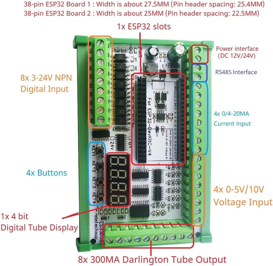
Figure 2.1: Detailed component layout of the ESP32 Expansion Board.
3. Setup Instructions
- Prepare the ESP32 Module: Ensure you have a compatible 38-pin ESP32 development board. This expansion board is designed to work specifically with 38-pin ESP32 modules.
- Insert ESP32 Module: Carefully align the 38-pin ESP32 module with the designated ESP32 slot on the expansion board. Gently press down until it is securely seated. Refer to Figure 3.1 for proper orientation.

Figure 3.1: Correct insertion of the 38-pin ESP32 module into the expansion board's slot.
- Power Connection: Connect a DC 12V-24V power supply to the power interface terminals on the board. Ensure correct polarity. The board's working voltage range is 12V to 24V DC.
- Initial Programming (Optional): If you are using the provided VSCode test codes, connect the ESP32 module to your computer via its USB port (if available on your ESP32 module) and upload the test firmware.
- Connect Peripherals:
- Digital Inputs: Connect NPN type low-level trigger sensors or switches to the 8 opto-isolated digital input terminals.
- Current Inputs: Connect 0/4-20mA current sensors to the 4 current input terminals.
- Voltage Inputs: Connect 0-5V or 0-10V voltage sensors to the 4 voltage input terminals.
- RS485: Connect RS485 devices to the RS485 A and B terminals for serial communication.
- Relay Outputs: Connect devices to be controlled by the 8 relay outputs. Each relay can handle up to 10A.
4. Operation
The eletechsup ESP32 Expansion Board operates under the control of the programmed 38-pin ESP32 module. Its functionality is entirely dependent on the firmware uploaded to the ESP32.
4.1 Basic Functionality
- Digital Tube Display: The 4-bit digital tube display can be programmed to show various information, such as status, sensor readings, or timer values.
- User Buttons: The 4 on-board buttons can be assigned custom functions within your ESP32 program, such as mode selection, manual control, or calibration.
- Relay Control: The 8 relays can be individually controlled by the ESP32 to switch external devices ON/OFF.
- Input Monitoring: The digital, current, and voltage inputs allow the ESP32 to monitor various environmental or system parameters.
- Communication: The RS485 interface enables communication with other industrial devices, while the ESP32's built-in WiFi and Ethernet capabilities (if supported by your ESP32 module) allow for network connectivity, including MQTT and web server applications.
4.2 Example Applications
With appropriate ESP32 programming, this board can be used for a wide range of applications, including:
- WiFi remote control switches
- WIFI current and voltage data collection
- Home automation and smart home DIY projects
- RS485 Master-Slave device control (e.g., replacing a PLC/MCU)
- Motor forward and reverse control
- Timing ON/OFF functions
- Power-up delay, trigger delay, and various cyclic delay functions
- Power sequencers
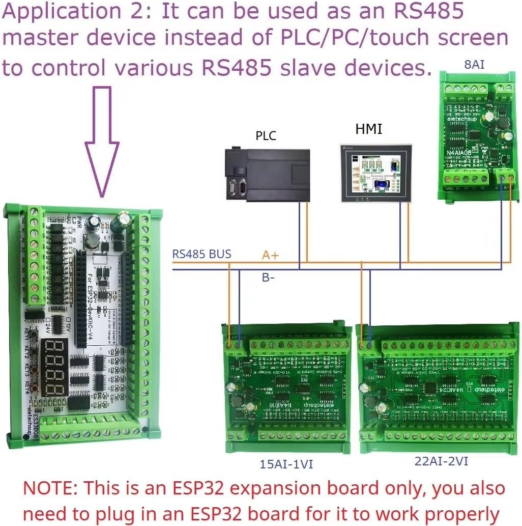
Figure 4.1: Application example demonstrating the board as an RS485 master device in an industrial control setup.
5. Maintenance
The eletechsup ESP32 Expansion Board is designed for reliable operation with minimal maintenance. Follow these guidelines to ensure longevity:
- Cleaning: Keep the board free from dust and debris. Use a soft, dry brush or compressed air for cleaning. Avoid using liquids or solvents.
- Environment: Operate the board within its specified temperature and humidity ranges. Avoid exposure to extreme temperatures, moisture, or corrosive environments.
- Power Supply: Always use a stable DC 12V-24V power supply. Unstable or incorrect voltage can damage the board.
- Connections: Periodically check all wiring connections to ensure they are secure and free from corrosion.
- Firmware Updates: If new firmware versions for your ESP32 module become available that enhance stability or add features relevant to this expansion board, consider updating.
6. Troubleshooting
If you encounter issues with your eletechsup ESP32 Expansion Board, refer to the following common problems and solutions:
| Problem | Possible Cause | Solution |
|---|---|---|
| Board does not power on (no LEDs). |
|
|
| PWR LED does not light up. | This is normal behavior. The PWR LED is controlled by an ESP32 IO port and requires programming to illuminate. | No action required. If you wish for the LED to light up, program the corresponding ESP32 IO pin. |
| Relays do not activate. |
|
|
| Analog input readings are inaccurate. |
|
|
| RS485 communication failure. |
|
|
For issues not covered here, please refer to the ESP32 documentation and community forums for programming-related support, as eletechsup provides limited technical support for custom code development.
7. Specifications
| Parameter | Value |
|---|---|
| Model | ES32A08 |
| Working Voltage | DC 12V-24V |
| Standby Current (Digital tube OFF) | 15mA |
| Standby Current (Digital tube ON) | 50mA |
| Current (1 relay open) | 76mA |
| Current (8 relays open) | 292mA |
| RS485 Interface | 1x |
| Opto-isolated Digital Inputs | 8x (low level trigger, NPN type) |
| Current Inputs | 4x (0/4-20mA) |
| Voltage Inputs | 4x (0-5V/10V) |
| User Buttons | 4x |
| Digital Tube Display | 1x (4-bit) |
| ESP32 Slot | 1x (for 38-pin ESP32) |
| Relay Outputs | 8x (10A) |
| Dimensions (Only Board) | 180 x 72 x 20 mm |
| Weight (Only Board) | 189g |
| Weight (With Shell) | 317g |
8. Warranty and Support
eletechsup provides a standard warranty for manufacturing defects. Please refer to the retailer's return policy for specific details regarding returns and exchanges. For technical inquiries related to hardware functionality or the provided test codes, you may contact eletechsup customer support through the vendor's contact information on the purchase platform.
Note:
As this is an expansion board requiring user-developed code for full functionality, eletechsup does not provide extensive technical support for custom programming, debugging user-written code, or advanced application development. Users are encouraged to utilize ESP32 community resources and documentation for programming assistance.