1. Introduction
This instruction manual provides essential information for the proper installation, operation, and maintenance of your eletechsup 8-channel NPN Input, PNP Output RS485 Modbus RTU PLC Remote IO Board (Model 25IOA08). Please read this manual thoroughly before using the device to ensure safe and efficient operation. This board is designed for industrial automation, smart home, and security system applications, offering reliable input acquisition and output control via RS485 Modbus RTU communication.
2. Product Overview
The eletechsup 25IOA08 is an 8-channel photoelectric isolated input and 8-channel DMOS PNP output module, designed for robust industrial control. It supports NPN input types and provides high-level PNP outputs with a drive current of up to 300mA per channel. Communication is handled via RS485 using the Modbus RTU protocol.
Key Features:
- Working Voltage: DC 7-25V (compatible with 9V, 12V, 24V systems).
- Working Current: 8-50mA.
- Inputs: 8 photoelectrically isolated NPN input ports.
- Outputs: 8 DMOS PNP outputs (high level output, 300mA drive current per channel).
- Output Modes: Supports Open, Close, Toggle (Self-locking), Latch (Inter-locking), Momentary (Non-locking), and Delay modes.
- Remote Control: Input ports can remotely control output ports on other boards via RS485.
- MODBUS Support: Command 1 supports 03, 06, 16 function codes. Command 2 supports 01, 02, 03, 05, 06, 15, 16 function codes.
- Delay Function: Maximum delay of 255 seconds under MODBUS command 1.
- Networking: Up to 64 devices can be supported in parallel in MODBUS command mode.
- Baud Rate: Default 9600BPS, configurable to 1200/2400/4800/19200/38400/57600/115200BPS.
- Protection: Photoelectric isolation on all I/O for surge protection.
What's in the Box:
- 1 x 8CH NPN Input PNP Output Switching Signal Acquisition Board (Model 25IOA08) with DIN Box.
3. Safety Information
- Always disconnect power before making any connections or disconnections.
- Ensure the power supply voltage is within the specified range (DC 7-25V). Incorrect voltage can damage the device.
- Observe proper polarity for power connections (VIN, GND).
- Avoid short circuits on input and output terminals.
- This device is intended for use by qualified personnel familiar with industrial control systems and electrical wiring.
- Do not expose the device to moisture, extreme temperatures, or corrosive environments.
4. Setup
This section details the physical installation and initial wiring of the 25IOA08 board.
4.1 Physical Installation
The 25IOA08 board comes with a DIN rail mountable box for easy integration into industrial control cabinets. Securely attach the module to a standard DIN rail in a location that allows for adequate ventilation and access to wiring terminals.
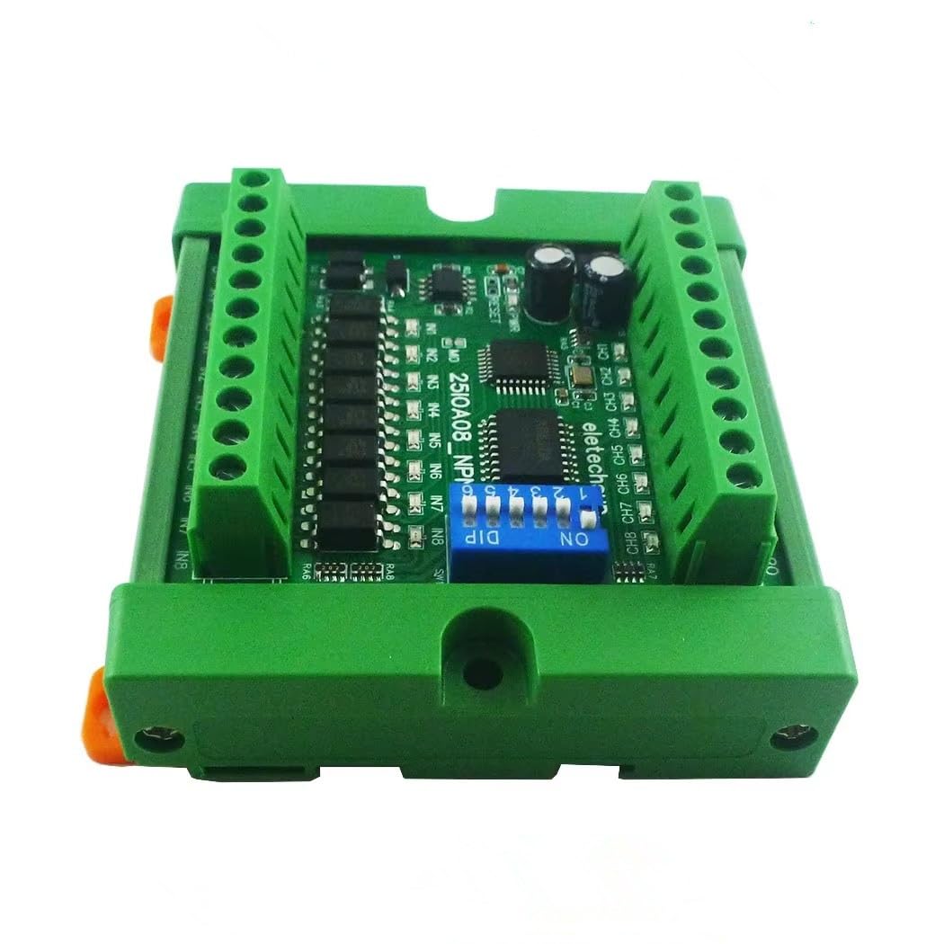
Figure 1: eletechsup 8CH NPN Input PNP Output RS485 Modbus RTU PLC Remote IO Board with DIN Case. This image shows the compact design of the 8-channel board housed in its green DIN rail enclosure, highlighting the screw terminals for connections and the DIP switch for configuration.
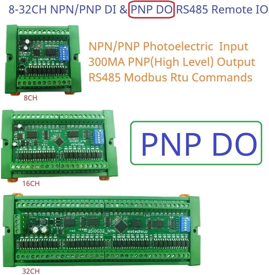
Figure 2: Different Channel Versions. This image illustrates the physical appearance of the 8-channel, 16-channel, and 32-channel versions of the eletechsup RS485 Modbus RTU IO boards, showing their varying lengths while maintaining a consistent width and height for DIN rail mounting.
4.2 Wiring Connections
Refer to the following diagrams for correct wiring of power, RS485 communication, NPN inputs, and PNP outputs.
4.2.1 Power Supply Connection
Connect a DC 7-25V power supply to the VIN and GND terminals. Ensure correct polarity.
4.2.2 RS485 Bus Connection
Connect the RS485 A+ and B- terminals to your RS485 master device (e.g., PLC, HMI, PC with RS485 converter). Maintain proper A+/B- polarity across all devices on the bus.
4.2.3 NPN Input Wiring
Connect your NPN sensors or switches to the IN1-IN8 terminals. The common ground for inputs is typically connected to the board's GND. NPN inputs are active low, meaning they detect a connection to ground.
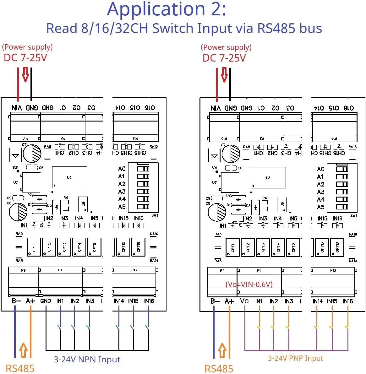
Figure 3: Application 2 - Reading NPN Switch Input via RS485 Bus. This diagram illustrates how to connect 3-24V NPN inputs to the board's input terminals (IN1-IN16) and how the board connects to a power supply (DC 7-25V) and an RS485 bus for reading input states.
4.2.4 PNP Output Wiring
Connect your loads (e.g., LEDs, relays, small motors) to the CH1-CH8 output terminals. PNP outputs provide a high-level voltage (close to supply voltage) when active. The maximum load current per channel is 300mA.
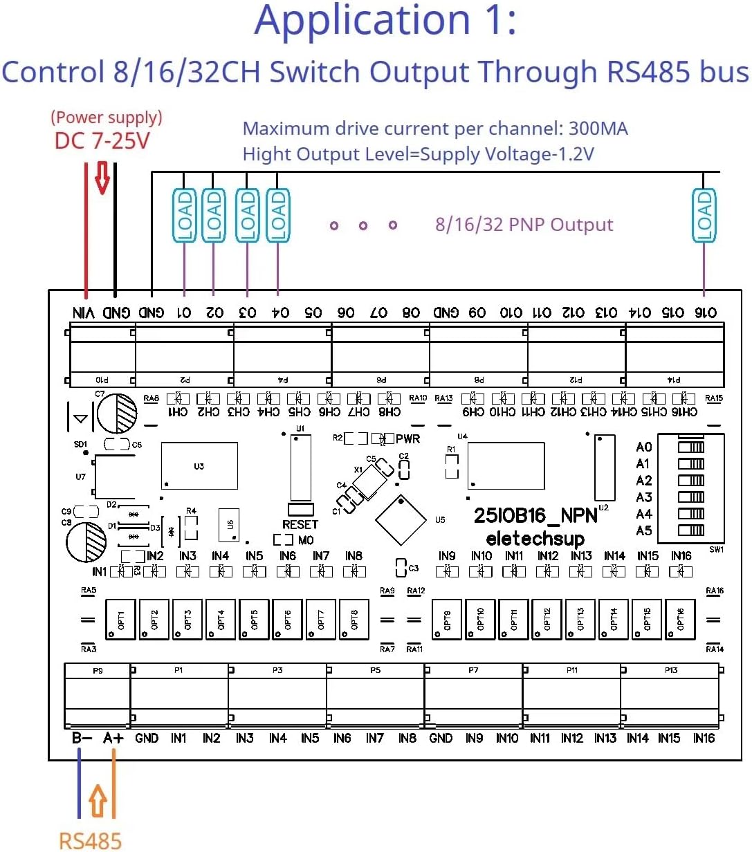
Figure 4: Application 1 - Controlling PNP Switch Output Through RS485 Bus. This diagram shows the wiring for connecting loads to the PNP output channels (CH1-CH16) and how the board receives power (DC 7-25V) and RS485 commands to control these outputs. Note the maximum drive current per channel is 300mA.
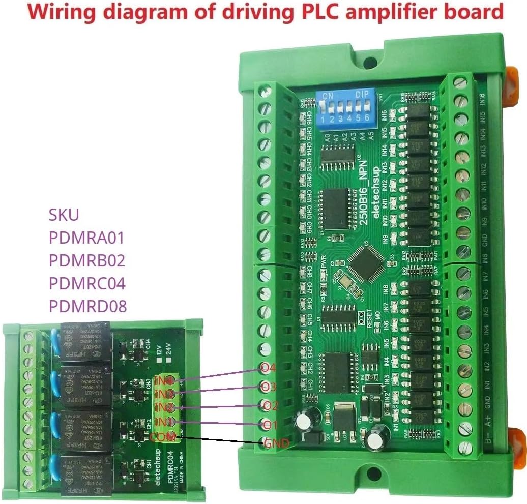
Figure 5: Wiring Diagram for Driving a PLC Amplifier Board. This image illustrates how the 25IOA08 board can be connected to an external relay board (e.g., PDMRC04) to amplify its output signals, allowing it to control higher power loads. The connections show output channels from the 25IOA08 driving the inputs of the relay board.
5. Operating Instructions
The 25IOA08 operates primarily through RS485 Modbus RTU commands. A Modbus master device is required to send commands to read inputs and control outputs.
5.1 Modbus Communication Settings
- Default Baud Rate: 9600BPS.
- Configurable Baud Rates: 1200, 2400, 4800, 19200, 38400, 57600, 115200 BPS. (Refer to product documentation or manufacturer for DIP switch settings if applicable for baud rate configuration).
- Modbus Address: Configurable via DIP switches on the board. Each board on the RS485 bus must have a unique address.
5.2 Modbus Function Codes
The board supports various Modbus RTU function codes for different operations:
- Read Coil Status (01h): Read the status of output coils.
- Read Discrete Inputs (02h): Read the status of input contacts.
- Read Holding Registers (03h): Read the content of holding registers (e.g., configuration parameters).
- Write Single Coil (05h): Write a single output coil (e.g., turn an output ON/OFF).
- Write Single Register (06h): Write a single holding register.
- Write Multiple Coils (0Fh / 15d): Write multiple output coils.
- Write Multiple Registers (10h / 16d): Write multiple holding registers.
Detailed Modbus register maps and command examples should be obtained from the manufacturer's specific protocol documentation for precise implementation.
5.3 Output Control Modes
The board supports six output modes, configurable via Modbus commands:
- Open/Close: Direct control of output state.
- Toggle (Self-locking): Output changes state with each command.
- Latch (Inter-locking): Outputs are interlocked, only one can be active at a time.
- Momentary (Non-locking): Output is active only while the command is held, or for a brief period.
- Delay: Output activates for a specified duration (up to 255 seconds).
6. Applications
The eletechsup 25IOA08 board is versatile and suitable for various applications:
- PLC IO expansion board
- RS485 Remote Control systems
- Smart Home and Home Automation systems
- PTZ IP Camera control
- Security Monitoring systems
- Identification systems
- LED Lamp Drivers
- Automatic curtain control
6.1 Remote IO Control Example
This application demonstrates how one board's inputs can remotely control another board's outputs via the RS485 bus.

Figure 6: Application 4 - Remote Input to Output Control. This diagram illustrates a setup where an NPN/PNP input board sends signals over an RS485 bus to a PNP output board, enabling remote control of loads. Both boards require a DC 7-25V power supply and share the same RS485 address for communication. Key notes include ensuring the RS485 address is the same, enabling the Remote IO Sender Register (Register 0x00F5 > 0), and enabling the Remote IO Receiver Register (Register 0x00F6 = 1).
6.2 Input Directly Controls Output Example
In this configuration, the board acts as an amplifier, where an input directly triggers a corresponding output without requiring explicit Modbus commands for each state change. This mode requires specific register configuration.
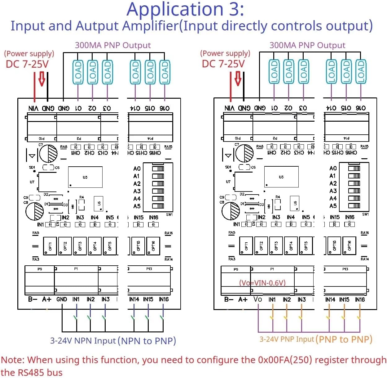
Figure 7: Application 3 - Input and Output Amplifier. This diagram shows how NPN inputs can directly control PNP outputs on the same board. Both input and output sections are powered by DC 7-25V. This functionality requires configuring the 0x00FA (250) register through the RS485 bus to enable direct input-to-output mapping.
7. Specifications
| Parameter | Value |
|---|---|
| Working Voltage | DC 7-25V |
| Working Current | 8-50mA |
| Input Channels | 8 (Photoelectrically isolated NPN) |
| Output Channels | 8 (DMOS PNP, high level output) |
| Max Output Drive Current | 300mA per channel |
| Communication Interface | RS485 |
| Protocol | Modbus RTU |
| Baud Rate | Default 9600BPS (Configurable: 1200-115200BPS) |
| Max Devices on Bus | 64 |
| Dimensions (with DIN Box) | 64 x 80 x 30 MM (for 8CH model) |
| Weight (with DIN Box) | 85g (for 8CH model) |
| Operating Temperature | Not specified (typically -20°C to 70°C for industrial) |
8. Maintenance
The eletechsup 25IOA08 board is designed for low maintenance. Follow these guidelines to ensure long-term reliability:
- Cleaning: Keep the board free from dust and debris. Use a soft, dry brush or compressed air for cleaning. Do not use liquid cleaners.
- Connections: Periodically check all wiring connections to ensure they are secure and free from corrosion. Loose connections can lead to intermittent operation or damage.
- Environment: Ensure the operating environment remains within specified conditions (temperature, humidity). Avoid exposure to strong electromagnetic interference.
- Firmware: Check the manufacturer's website for any available firmware updates. Follow update instructions carefully if performing an update.
9. Troubleshooting
If you encounter issues with your 25IOA08 board, refer to the following troubleshooting steps:
9.1 No Power Indication
- Check Power Supply: Verify that the DC 7-25V power supply is connected correctly and providing the specified voltage.
- Polarity: Ensure VIN and GND connections are not reversed.
- Fuses: Check for any blown fuses in the power supply circuit.
9.2 No RS485 Communication
- Wiring: Verify RS485 A+ and B- connections are correct and not swapped.
- Baud Rate: Ensure the baud rate of the board matches the baud rate configured on the Modbus master.
- Modbus Address: Confirm the board's Modbus address is unique and matches the address used by the master.
- Termination Resistors: For long RS485 bus lines, ensure proper termination resistors (typically 120 Ohm) are installed at both ends of the bus.
- Bus Activity: Use an RS485 analyzer or oscilloscope to check for data activity on the bus.
9.3 Inputs Not Responding
- Wiring: Check NPN input wiring for correct connections and ensure the sensor/switch is functioning.
- Input Type: Confirm the board is configured for NPN inputs (if configurable, though this model is specified as NPN input).
- Modbus Read Command: Verify that the Modbus master is sending the correct function code (e.g., 02h Read Discrete Inputs) and register address to read the input states.
9.4 Outputs Not Activating
- Wiring: Check PNP output wiring. Ensure loads are connected correctly and within the 300mA current limit.
- Load Power: Verify that the load has its own power supply if required, or that the board's output can supply enough power.
- Modbus Write Command: Ensure the Modbus master is sending the correct function code (e.g., 05h Write Single Coil, 0Fh Write Multiple Coils) and register address to control the outputs.
- Output Mode: Confirm the desired output mode (e.g., Open/Close, Momentary) is correctly configured via Modbus.
10. Warranty and Support
eletechsup products are typically covered by a limited warranty against manufacturing defects. For specific warranty terms and duration, please refer to the product packaging or the official eletechsup website.
For technical support, troubleshooting assistance, or inquiries regarding product functionality, please contact eletechsup customer service through their official channels. When contacting support, please provide your product model (25IOA08) and a detailed description of the issue.
eletechsup Store: Visit the eletechsup Store on Amazon