ROXIFETA A7105/XL7105-D03
ROXIFETA A7105/XL7105-D03 Module User Manual
Model: A7105 / XL7105-D03
1. Introduction
This manual provides comprehensive instructions for the installation, operation, and maintenance of the ROXIFETA A7105/XL7105-D03 module. This high-quality electronic component is designed for various applications requiring robust and reliable wireless communication, supporting protocols such as Deviation, Galee, and Flysky.
2. Safety Information
Please read and understand all safety precautions before handling or operating the module. Failure to do so may result in damage to the device or personal injury.
- Ensure proper electrostatic discharge (ESD) precautions are taken when handling the module to prevent damage to sensitive components.
- Do not expose the module to extreme temperatures, humidity, or corrosive environments.
- Verify correct voltage and current supply before powering the module. Incorrect power can lead to permanent damage.
- Keep the module away from water and other liquids.
- Only qualified personnel should attempt repairs or modifications.
3. Package Contents
Verify that all items are present and in good condition upon opening the package.
- 2 x A7105/XL7105-D03 Modules
- (Optional) Antenna(s) if included with the module.
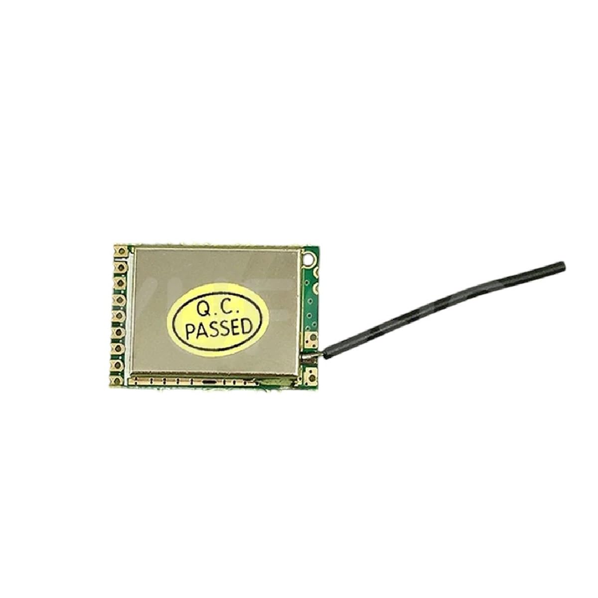
Image: A single A7105/XL7105-D03 module, showing its compact size and integrated antenna. This module is a key component for various wireless communication applications.
4. Product Overview and Features
The A7105/XL7105-D03 module is a versatile radio frequency (RF) transceiver designed for reliable wireless data transmission. It supports multiple protocols, making it suitable for a wide range of applications, including remote control systems and IoT devices.
Key Features:
- High-Quality Electronics Components: Constructed with durable materials for reliable and long-lasting performance.
- Multi-Protocol Support: Compatible with Deviation, Galee, and Flysky protocols.
- Versatile Applications: Suitable for industrial, automotive, and household electronics.
- Compact Design: Small form factor for easy integration into various projects.

Image: An isometric illustration depicting a variety of semiconductor electronic components, such as integrated circuits, resistors, capacitors, and LEDs. This illustrates the diverse components that make up modern electronic devices.

Image: A collection of various electronic components, including microchips, resistors, capacitors, and diodes, highlighting the complexity and variety of parts used in electronic assemblies.
5. Setup and Installation
This section outlines the steps for properly setting up and installing your A7105/XL7105-D03 module.
5.1 Pinout Diagram (Conceptual)
While a specific pinout diagram is not provided, typical A7105 modules feature standard SPI (Serial Peripheral Interface) communication pins and power supply pins. Refer to the module's datasheet for exact pin configurations.
- VCC: Power supply input (typically 3.3V).
- GND: Ground connection.
- CS (Chip Select): SPI chip select pin.
- SCK (Serial Clock): SPI clock pin.
- MOSI (Master Out Slave In): SPI data input pin.
- MISO (Master In Slave Out): SPI data output pin.
- IRQ (Interrupt Request): Optional interrupt pin.
5.2 Connection Steps:
- Prepare Your Development Board: Ensure your microcontroller or development board (e.g., Arduino, ESP32) is powered off.
- Connect Power: Connect the VCC pin of the A7105 module to the 3.3V output of your development board and GND to the ground.
- Connect SPI Pins:
- Connect A7105 CS to your board's CS pin.
- Connect A7105 SCK to your board's SCK pin.
- Connect A7105 MOSI to your board's MOSI pin.
- Connect A7105 MISO to your board's MISO pin.
- (Optional) Connect IRQ: If using interrupt-driven communication, connect the IRQ pin to an interrupt-capable pin on your development board.
- Attach Antenna: Securely attach the provided antenna to the module's antenna connector.
- Power On: Once all connections are verified, power on your development board.
6. Operating Instructions
Operating the A7105/XL7105-D03 module typically involves programming a microcontroller to communicate with it via SPI and implement the desired wireless protocol.
6.1 Protocol Implementation:
The module supports Deviation, Galee, and Flysky protocols. Implementation requires specific firmware or libraries for your microcontroller. Resources for these protocols are often found in open-source communities related to RC (Radio Control) and drone projects.
- Deviation Protocol: Often used in multi-protocol radio transmitters. Requires specific register configurations on the A7105.
- Flysky Protocol: Common in Flysky brand RC systems. Ensure your implementation matches the specific version (e.g., AFHDS, AFHDS 2A).
- Galee Protocol: Less common, specific documentation may be required.
6.2 Basic Communication Flow:
- Initialization: Configure the A7105 registers for frequency, data rate, power output, and protocol-specific settings.
- Transmit Mode: Load data into the transmit buffer and command the module to send.
- Receive Mode: Set the module to receive mode and poll for incoming data or wait for an IRQ signal.
- Error Handling: Implement checks for transmission errors, packet loss, or invalid data.
7. Maintenance
The A7105/XL7105-D03 module is designed for durability and requires minimal maintenance. However, following these guidelines can extend its lifespan and ensure optimal performance:
- Keep Clean: Periodically clean the module with a soft, dry, anti-static cloth. Avoid using liquids or harsh chemicals.
- Environmental Control: Store and operate the module within its specified temperature and humidity ranges.
- Secure Connections: Regularly check all connections (power, SPI, antenna) to ensure they are secure and free from corrosion.
- Firmware Updates: If using custom firmware, ensure it is up-to-date to benefit from bug fixes and performance improvements.
8. Troubleshooting
This section addresses common issues you might encounter and provides potential solutions.
| Problem | Possible Cause | Solution |
|---|---|---|
| Module not powering on. | Incorrect voltage, loose power connection, faulty module. | Verify VCC and GND connections. Check power supply voltage. Test with a known good power source. |
| No communication via SPI. | Incorrect SPI wiring, incorrect SPI mode/speed, module not initialized. | Double-check CS, SCK, MOSI, MISO connections. Ensure SPI clock polarity and phase are correct. Verify module initialization code. |
| Poor wireless range or no signal. | Antenna not connected, antenna damaged, environmental interference, incorrect frequency/power settings. | Ensure antenna is securely attached. Check for physical damage to the antenna. Test in a less noisy environment. Verify RF settings in your code. |
| Protocol not working (e.g., Flysky). | Incorrect protocol implementation, incompatible firmware, wrong binding procedure. | Review protocol documentation. Ensure your firmware matches the required protocol version. Follow the correct binding sequence for your receiver. |
9. Specifications
The following are general specifications for the A7105/XL7105-D03 module. Refer to the manufacturer's datasheet for detailed technical parameters.
- Model: A7105 / XL7105-D03
- Manufacturer: ROXIFETA
- ASIN: B0DXL2YDPP
- Supported Protocols: Deviation, Galee, Flysky
- Interface: SPI
- Operating Voltage: Typically 1.9V - 3.6V (confirm with datasheet)
- Frequency Band: 2.4 GHz ISM band
- Date First Available: February 18, 2025
10. Warranty and Support
ROXIFETA is committed to providing high-quality products and excellent customer service.
10.1 Money-Back Guarantee:
Confidence in our product quality is backed by a money-back guarantee. Please refer to your purchase terms for specific details regarding returns and refunds.
10.2 Exceptional Customer Support:
Our knowledgeable team is available to assist you with any questions or concerns regarding the A7105/XL7105-D03 module. For support, please contact your retailer or visit the ROXIFETA official support channels.
Related Documents - A7105/XL7105-D03
 |
RadioMaster TX16S Quick Start Guide - RC Transmitter Get started with the RadioMaster TX16S 2.4GHz remote control system. This guide covers setup, safety, specifications, and features for this versatile RC transmitter, including detailed control descriptions and charging precautions. |
 |
4-in-1 Multi-Protocol TX Module with Antenna: CC2500, NRF24L01, A7105, CTRF6936 This document details the 4-in-1 Multi-protocol TX Module, integrating CC2500, NRF24L01, A7105, and CYRF6936 RF chips. It supports numerous remote control protocols for various RC craft, offering flexible control and enhanced user experience. Includes technical specifications, operating parameters, and detailed protocol mapping. |
 |
iRangeX IRX4 Lite 4-in-1 RC Transmitter Module: Protocol Compatibility and Usage Guide Comprehensive guide to the iRangeX IRX4 Lite 2.4GHz 4-in-1 STM32 Multiprotocol TX Module, detailing supported radio control protocols, RF chip compatibility, technical specifications, and step-by-step usage instructions for RC hobbyists. |
 |
RadioMaster 4IN1 Multi-Protocol External Module Comprehensive details on the RadioMaster 4IN1 multi-protocol external module, integrating CC2500, NRF24L01, A7105, and CYRF6936 RF chips. Designed for OpenTX and EdgeTX systems, it enables connection with most mainstream protocols. Includes technical specifications and an extensive list of supported protocols for various RC transmitters. |
 |
Eachine TX16S Radio Control System User Manual Comprehensive user manual for the Eachine TX16S 2.4GHz 16-channel radio control system, covering introduction, safety instructions, model and protocol selection, remote control overview, specifications, firmware updates, and charging precautions. |
 |
RX4 4-IN-1 Multi-Protocol RF Module - iRangeX Detailed specifications and operating instructions for the iRangeX RX4 4-in-1 Multi-Protocol RF Module, compatible with CC2500, CYRF6936, A7105, and NRF24L01+ protocols. |