1. Introduction
This manual provides comprehensive instructions for the assembly, operation, and maintenance of your COCEMORINI DS1302 DIY Rotating Digital LED Display Module Alarm Electronic Digital Clock Kit. This kit is designed for enthusiasts and learners interested in electronics, offering a hands-on experience in building a functional digital clock with a rotating LED display and alarm features. Please read all instructions carefully before beginning assembly.
2. Product Overview and Components
The DS1302 DIY kit includes all necessary electronic components and structural parts to construct a digital clock. Familiarize yourself with the components before starting the assembly process.
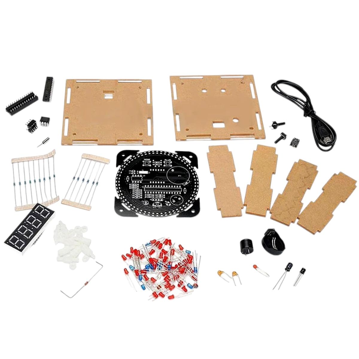
Image 2.1: All components included in the DS1302 DIY kit. This includes the main circuit board, acrylic casing parts, various resistors, capacitors, LEDs, integrated circuits (ICs), a 7-segment display, a USB power cable, and fasteners.
Kit Contents:
- Main Printed Circuit Board (PCB)
- Acrylic Casing Panels and Fasteners
- DS1302 Real-Time Clock IC
- Microcontroller (e.g., 51 SCM compatible)
- LEDs (various colors for display and indicators)
- Resistors and Capacitors
- Transistors and Diodes
- 7-Segment LED Display Module
- Push Buttons for setting
- Buzzer for alarm function
- USB Power Cable
3. Setup and Assembly Instructions
Assembly of this kit requires basic soldering skills and careful attention to detail. Ensure you have a clean workspace and appropriate tools (soldering iron, solder, wire cutters, multimeter, safety glasses).
Safety Precautions:
- Always wear safety glasses when soldering.
- Work in a well-ventilated area to avoid inhaling solder fumes.
- Ensure your soldering iron is properly grounded and handled with care.
- Do not apply power until all components are correctly installed and checked.
Assembly Steps:
- Component Identification: Carefully identify all components using the provided circuit diagram (if included) and component list. Pay attention to resistor color codes and capacitor values.
- Solder Resistors and Diodes: Start by soldering the smallest components first. Insert resistors and diodes into their designated positions on the PCB, ensuring correct polarity for diodes. Bend leads to secure them, then solder and trim excess leads.
- Solder Capacitors and Transistors: Proceed with capacitors (observing polarity for electrolytic capacitors) and transistors.
- Solder IC Sockets (if applicable) and ICs: If IC sockets are provided, solder them first. Then carefully insert the Integrated Circuits (ICs) into their sockets, ensuring correct orientation (notch or dot aligns with the PCB marking). If no sockets, solder the ICs directly, paying close attention to pin 1 orientation.
- Solder LEDs and 7-Segment Display: Solder the individual LEDs and the 7-segment display module. Ensure correct polarity for LEDs (longer lead is positive, shorter is negative).
- Solder Buttons and Buzzer: Install the push buttons and the buzzer.
- Solder Power Connector: Solder the USB power connector or DC jack.
- Initial Power Test: Before assembling the casing, perform a quick power test. Connect the 5V power supply. Check for any smoke, unusual smells, or excessive heat. If the display lights up, proceed. If not, disconnect power immediately and troubleshoot.
- Assemble Acrylic Casing: Carefully peel off any protective film from the acrylic panels. Assemble the casing around the completed PCB using the provided screws and standoffs. Ensure all parts fit snugly and are aligned correctly.
4. Operating Instructions
Once assembled, your DS1302 Digital Clock is ready for operation.
Powering On:
- Connect the provided USB power cable to the clock's power input and a 5V USB power adapter (not included) or a computer USB port.
- The LED display should illuminate, showing the current time.
Setting Time and Alarm:
The clock typically features several push buttons for setting. While specific button functions may vary slightly based on firmware, the general procedure is as follows:
- Mode Button: Press this button to cycle through different modes: Time Display, Date Display, Alarm Setting, Time Setting.
- Up/Down Buttons: Use these buttons to adjust values (hours, minutes, day, month, year) when in a setting mode.
- Confirm/Set Button: Press this button to confirm a setting or move to the next parameter.
- Alarm On/Off: There may be a dedicated button or a combination of buttons to enable or disable the alarm. When the alarm is active, an indicator (e.g., a small LED or symbol on the display) may light up.
Refer to the specific programming or user guide provided with the microcontroller's firmware for precise button functionalities if available.
Rotating Display Feature:
The clock features a rotating LED display. This means the time or other information may appear to rotate or scroll across the display, providing a dynamic visual effect. This is an automatic function and does not typically require user input to activate.
5. Maintenance
To ensure the longevity and proper functioning of your digital clock kit, follow these simple maintenance guidelines:
- Cleaning: Use a soft, dry cloth to gently wipe the acrylic casing and display. Avoid using abrasive cleaners or solvents, which can damage the acrylic or electronic components.
- Environment: Keep the clock in a dry environment, away from direct sunlight, extreme temperatures, and high humidity.
- Power Supply: Always use a stable 5V DC power supply. Avoid using power sources that provide fluctuating voltage or current.
- Handling: Handle the assembled clock with care to prevent damage to the electronic components or the casing.
6. Troubleshooting
If you encounter issues with your DS1302 Digital Clock, refer to the following troubleshooting steps:
- Clock Does Not Power On:
- Check the power connection. Ensure the USB cable is securely plugged into both the clock and the power source.
- Verify the power source is providing 5V. Try a different USB port or power adapter.
- Inspect the power input solder joints on the PCB for any cold joints or short circuits.
- Display is Blank or Incorrect:
- Check the solder joints for the 7-segment display and individual LEDs.
- Ensure the ICs are correctly seated in their sockets (if applicable) and oriented properly.
- Verify that all resistors and capacitors are in their correct positions and values.
- Buttons Do Not Respond:
- Check the solder joints for the push buttons.
- Ensure the buttons themselves are not stuck or damaged.
- Alarm Does Not Sound:
- Verify that the alarm function is enabled in the settings.
- Check the buzzer's solder connections and ensure it is not damaged.
- Time Drifts or is Incorrect:
- Ensure the DS1302 Real-Time Clock IC is correctly installed and functioning.
- Check the crystal oscillator connected to the DS1302 for proper soldering and function.
If problems persist after attempting these steps, carefully re-examine all solder joints and component placements against the circuit diagram.
7. Specifications
- Model: DS1302 DIY Rotating Digital LED Display Module
- Input Voltage: 5V DC (via USB)
- Display Type: Rotating LED 7-Segment Display
- Functions: Digital Clock, Alarm, Date Display
- Microcontroller: Compatible with 51 SCM (Single-Chip Microcomputer)
- Real-Time Clock (RTC) IC: DS1302
- Manufacturer: COCEMORINI
- ASIN: B0DXJVCJW7
- First Available: February 18, 2025
8. Warranty and Support
COCEMORINI stands by the quality of its products. This kit is made with high-quality electronic components designed for reliable performance. We offer a money-back guarantee, reflecting our commitment to quality.
For any questions, concerns, or technical assistance regarding your DS1302 DIY kit, please contact COCEMORINI customer support. Our knowledgeable team is ready to assist you to ensure the best possible experience with your product.
Please refer to your purchase documentation or the seller's contact information on the platform where you purchased the product for specific support channels.


