1. Introduction
This user manual provides detailed instructions for the ANENG 3-in-1 Electrical Diagnostics Kit, which includes the ANENG SZ301 Digital Multimeter, ANENG TH202 Infrared Thermometer, and ANENG B15 Voltage Detector. This comprehensive kit is designed for both household and industrial applications, offering precise measurements and reliable safety features for various electrical and temperature-related tasks.

Figure 1: The complete ANENG 3-in-1 Electrical Diagnostics Kit, featuring the digital multimeter, infrared thermometer, and voltage detector, accompanied by test leads and batteries.
2. Safety Information
Always read and understand all safety warnings and operating instructions before using this product. Failure to follow these instructions may result in electric shock, fire, serious injury, or death.
2.1 General Safety Precautions
- Do not operate the devices if they appear damaged or are not functioning properly.
- Keep hands and fingers away from the probe tips when making measurements.
- Use caution when working with voltages above 30V AC RMS, 42V peak, or 60V DC. These voltages pose a shock hazard.
- Always disconnect power to the circuit before making resistance, continuity, or diode measurements.
- Ensure the correct function and range are selected before making any measurement.
- Replace batteries promptly when the low battery indicator appears.
2.2 Multimeter (SZ301) Specific Safety
- Do not exceed the maximum input limits for each range.
- Never connect the test leads to a voltage source when the rotary switch is set to current, resistance, or diode mode.
- Ensure the test leads are fully inserted into the correct input jacks.
- The multimeter features ceramic fuses and overload protection. Do not bypass these safety features.
2.3 Infrared Thermometer (TH202) Specific Safety
- CAUTION: Do not point the laser directly at eyes or indirectly off reflective surfaces.
- This device is for surface temperature measurement only. It is not intended for human or animal body temperature measurement.
- Do not use the thermometer near explosive gases, vapor, or dust.
2.4 Voltage Detector (B15) Specific Safety
- The B15 is a non-contact voltage detector. It is designed to indicate the presence of AC voltage. Always verify with a known live circuit before use.
- Do not rely solely on the voltage detector for determining if a circuit is de-energized. Always follow Lockout/Tagout procedures where applicable.
3. Package Contents
Verify that all items are present and in good condition upon opening the package:
- 1 x ANENG SZ301 Digital Multimeter
- 1 x ANENG TH202 Infrared Thermometer
- 1 x ANENG B15 Voltage Detector
- 1 x Pair of Multimeter Test Leads
- 3 x AAA Batteries (for TH202)
- 2 x AAA Batteries (for SZ301)
- 2 x AAA Batteries (for B15)
- 1 x User Manual (this document)
4. Component Overview
4.1 ANENG SZ301 Digital Multimeter
The SZ301 is a compact and versatile digital multimeter designed for measuring AC/DC voltage, AC/DC current, resistance, continuity, diode, capacitance, and frequency. It features a large LCD display with a 4000-count resolution and a rotary dial for easy function selection.

Figure 2: The rotary dial of the ANENG SZ301 Multimeter, highlighting its various measurement functions.
4.2 ANENG TH202 Infrared Thermometer
The TH202 is a non-contact infrared thermometer capable of measuring surface temperatures from -50°C to 600°C (-58°F to 1112°F). It features a 12:1 distance-to-spot ratio, adjustable emissivity, and a backlit LCD display for clear readings. The integrated laser pointer assists in targeting the measurement area.

Figure 3: Key features of the ANENG TH202 Infrared Thermometer, including its display, laser, and measurement capabilities.
4.3 ANENG B15 Voltage Detector
The B15 is a non-contact AC voltage detector designed to quickly identify live wires, detect line breakpoints, and perform battery detection. It features an LCD display and a flashlight for use in dark environments, providing a safe and convenient way to check for voltage presence.
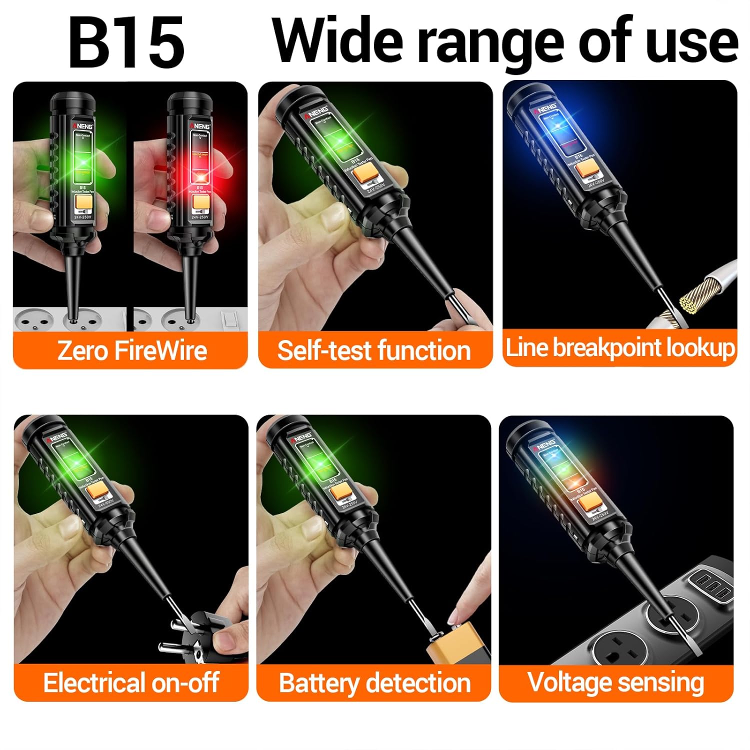
Figure 4: The ANENG B15 Voltage Detector showcasing its wide range of applications and detection capabilities.
5. Setup
5.1 Battery Installation
All three devices require AAA batteries for operation. Please ensure correct polarity when inserting batteries.
- ANENG SZ301 Digital Multimeter: Open the battery compartment cover on the back of the multimeter. Insert 2 x AAA batteries, observing the polarity markings (+/-). Close the cover securely.
- ANENG TH202 Infrared Thermometer: Open the battery compartment located in the handle. Insert 3 x AAA batteries, ensuring correct polarity. Close the compartment.
- ANENG B15 Voltage Detector: Unscrew the cap at the bottom of the detector. Insert 2 x AAA batteries, observing the polarity markings. Replace the cap and tighten.
6. Operating Instructions
6.1 ANENG SZ301 Digital Multimeter
6.1.1 Power On/Off
Rotate the central dial from the 'OFF' position to any desired measurement function to power on the multimeter. To power off, rotate the dial back to the 'OFF' position.
6.1.2 Function Selection
Use the large rotary dial to select the desired measurement function (e.g., V~ for AC Voltage, V- for DC Voltage, Ω for Resistance, etc.). The 'SEL' button can be used to switch between AC/DC modes or other sub-functions within a single dial position.
6.1.3 Measuring AC/DC Voltage
- Insert the red test lead into the 'VΩmAÅ' jack and the black test lead into the 'COM' jack.
- Rotate the dial to the 'V~' (AC Voltage) or 'V-' (DC Voltage) position.
- Touch the test probes to the circuit points where voltage is to be measured (in parallel with the load).
- Read the voltage value on the LCD display.

Figure 5: The ANENG SZ301 Multimeter connected to a wall outlet to measure AC voltage.
6.1.4 Measuring AC/DC Current
- For current up to 10A, insert the red test lead into the '10A MAX' jack. For current up to 200mA, use the 'VΩmAÅ' jack. Insert the black test lead into the 'COM' jack.
- Rotate the dial to the '10A' or '200mA' position. Use 'SEL' to switch between AC and DC current.
- CAUTION: Connect the multimeter in series with the circuit to measure current. Never connect it in parallel with a voltage source.
- Read the current value on the LCD display.

Figure 6: The ANENG SZ301 Multimeter connected in series to measure AC current flowing through a light bulb circuit.
6.1.5 Measuring Resistance
- Insert the red test lead into the 'VΩmAÅ' jack and the black test lead into the 'COM' jack.
- Rotate the dial to the 'Ω' position.
- Ensure the circuit is de-energized. Touch the probes across the component to be measured.
- Read the resistance value on the LCD display.
6.1.6 Continuity Test
- Insert the red test lead into the 'VΩmAÅ' jack and the black test lead into the 'COM' jack.
- Rotate the dial to the 'Å' (Continuity/Diode) position. Use 'SEL' to select continuity.
- Ensure the circuit is de-energized. Touch the probes to the ends of the circuit or component.
- A continuous beep indicates a good connection (low resistance).
6.1.7 Diode Test
- Insert the red test lead into the 'VΩmAÅ' jack and the black test lead into the 'COM' jack.
- Rotate the dial to the 'Å' (Continuity/Diode) position. Use 'SEL' to select diode test.
- Ensure the circuit is de-energized. Connect the red probe to the anode and the black probe to the cathode of the diode.
- The display will show the forward voltage drop. Reverse the probes; an open circuit (OL) indicates a good diode.
6.1.8 Capacitance Measurement
- Insert the red test lead into the 'VΩmAÅ' jack and the black test lead into the 'COM' jack.
- Rotate the dial to the 'µF' (Capacitance) position.
- Ensure the capacitor is fully discharged before testing. Connect the probes across the capacitor terminals.
- Read the capacitance value on the LCD display.
6.1.9 Frequency Measurement
- Insert the red test lead into the 'VΩmAÅ' jack and the black test lead into the 'COM' jack.
- Rotate the dial to the 'Hz' (Frequency) position.
- Connect the probes to the circuit where frequency is to be measured.
- Read the frequency value on the LCD display.
6.2 ANENG TH202 Infrared Thermometer
6.2.1 Power On/Off
Press the trigger to power on the thermometer. It will automatically power off after 15 seconds of inactivity to conserve battery life.
6.2.2 Taking Temperature Readings
- Point the thermometer at the target surface.
- Press and hold the trigger. The laser pointer will activate to indicate the measurement spot.
- The temperature reading will appear on the display instantly. Release the trigger to hold the reading.

Figure 7: Using the ANENG TH202 Infrared Thermometer to detect overheating in an automotive engine.
6.2.3 Understanding Distance-to-Spot Ratio (D:S)
The TH202 has a 12:1 D:S ratio. This means that at a distance of 12 units from the target, the measurement spot diameter will be 1 unit. For accurate readings, ensure the target spot is entirely within the measurement area. Measure closer to smaller objects.
6.2.4 Adjusting Emissivity
Emissivity (ε) is the ability of a material to emit thermal energy. Different materials have different emissivities. For most organic materials, painted surfaces, or water, an emissivity of 0.95 is suitable. For highly reflective surfaces like polished metals, emissivity may need to be adjusted for accurate readings. Refer to an emissivity table for specific materials. Press the 'MODE' button to enter emissivity adjustment mode.
6.2.5 Unit Switching (°C/°F)
Press the '°C/°F' button to toggle between Celsius and Fahrenheit temperature units.

Figure 8: Internal and external features of the ANENG TH202 Infrared Thermometer, including its smart circuit board and laser.

Figure 9: Examples of diverse applications for the ANENG TH202 Infrared Thermometer in home and industrial settings.
6.3 ANENG B15 Voltage Detector
6.3.1 Power On/Off
Press the power button to turn on the B15. It will automatically power off after a period of inactivity.
6.3.2 Non-Contact AC Voltage Detection
- Hold the tip of the detector near the wire, outlet, or electrical component.
- If AC voltage is detected, the LED indicator will light up and an audible alarm will sound. The intensity of the indication (color/sound) may vary with voltage strength.
6.3.3 Live Wire / Zero FireWire Detection
- Insert the tip of the detector into the live (hot) slot of an outlet or touch it to a live wire. The detector will indicate the presence of voltage.
- Insert the tip into the neutral slot or touch it to a neutral wire. The detector should not indicate voltage.
6.3.4 Line Breakpoint Lookup
- For a live wire, slowly move the detector along the wire. The indication will stop at the point where the wire is broken.
6.3.5 Battery Detection
- The B15 can also be used to quickly check the charge of small batteries (e.g., AAA, AA). Touch the tip to the positive terminal and the metal clip to the negative terminal. The indicator will show the battery status.
7. Maintenance
7.1 Cleaning
Wipe the devices with a dry, clean cloth. Do not use abrasive cleaners or solvents. Ensure no moisture enters the device.
7.2 Battery Replacement
When the low battery indicator appears on any device, replace the batteries promptly to ensure accurate readings and proper operation. Refer to Section 5.1 for battery installation instructions.
7.3 Storage
Store the devices in a cool, dry place, away from direct sunlight and extreme temperatures. If storing for an extended period, remove the batteries to prevent leakage.
8. Troubleshooting
| Problem | Possible Cause | Solution |
|---|---|---|
| Multimeter / Thermometer / Detector does not power on. | Dead or incorrectly installed batteries. | Check battery polarity and replace with fresh batteries. |
| Multimeter shows 'OL' (Overload) or '1'. | Measurement range exceeded or open circuit. | Select a higher range or check for an open circuit in the component/wire. |
| Infrared Thermometer readings are inaccurate. | Incorrect emissivity setting; target too small or too far; lens dirty. | Adjust emissivity for the target material; ensure target fills the spot; clean the lens. |
| Voltage Detector gives false positives/negatives. | Interference from other electrical fields; low battery; thick insulation. | Test on a known live circuit first; replace batteries; be aware of insulation thickness. |
| Multimeter display is dim or flickering. | Low battery. | Replace batteries. |
9. Specifications
9.1 ANENG SZ301 Digital Multimeter
| Parameter | Value |
|---|---|
| Display | 4000 Counts LCD |
| DC Voltage Accuracy | ±1% |
| AC Voltage Range | Up to 600V |
| DC Voltage Range | Up to 600V |
| AC/DC Current Range | Up to 10A |
| Resistance Range | Up to 200MΩ |
| Capacitance Range | Up to 200mF |
| Power Source | 2 x AAA Batteries |
| Safety Features | Ceramic fuses, Overload protection, Silicone-shielded probes |
9.2 ANENG TH202 Infrared Thermometer
| Parameter | Value |
|---|---|
| Temperature Range | -50°C to 600°C (-58°F to 1112°F) |
| Accuracy | ±1.5% |
| Response Time | 0.5 seconds |
| Distance-to-Spot Ratio (D:S) | 12:1 |
| Emissivity | Adjustable |
| Laser Targeting | Yes |
| Display | High resolution color LCD with backlight |
| Auto Power Off | 15 seconds |
| Power Source | 3 x AAA Batteries |
9.3 ANENG B15 Voltage Detector
| Parameter | Value |
|---|---|
| Voltage Detection Range | 24V-250V AC |
| Detection Type | Non-contact |
| Features | LCD Display, Flashlight, Ground wire detection |
| Power Source | 2 x AAA Batteries |
10. Warranty and Support
ANENG products are manufactured to high-quality standards. For specific warranty information, including duration and terms, please refer to the product packaging or the official ANENG website. Keep your purchase receipt as proof of purchase.
For technical support, troubleshooting assistance, or warranty claims, please visit the official ANENG store on Amazon or their dedicated support channels. You can find the ANENG store at: ANENG Store on Amazon.
Please have your product model number (SZ301, TH202, B15) and purchase details ready when contacting support.


